Team:Bologna/Modeling
From 2008.igem.org
Revision as of 16:47, 14 October 2008 by Mavi.amaduzzi (Talk | contribs)
| HOME | THE PROJECT | THE TEAM | PARTS SUBMITTED TO THE REGISTRY | MODELING | NOTEBOOK | BIOSAFETY |
|---|
Mathematical Model
The behavior of this device and the conditions for bistability can be understood using the following differential equations for the network:
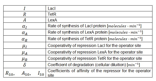
Where:
α = promoter activity and rbs
δ = coefficient of degradation (cellular diluition)
μ = coefficient of cooperativity
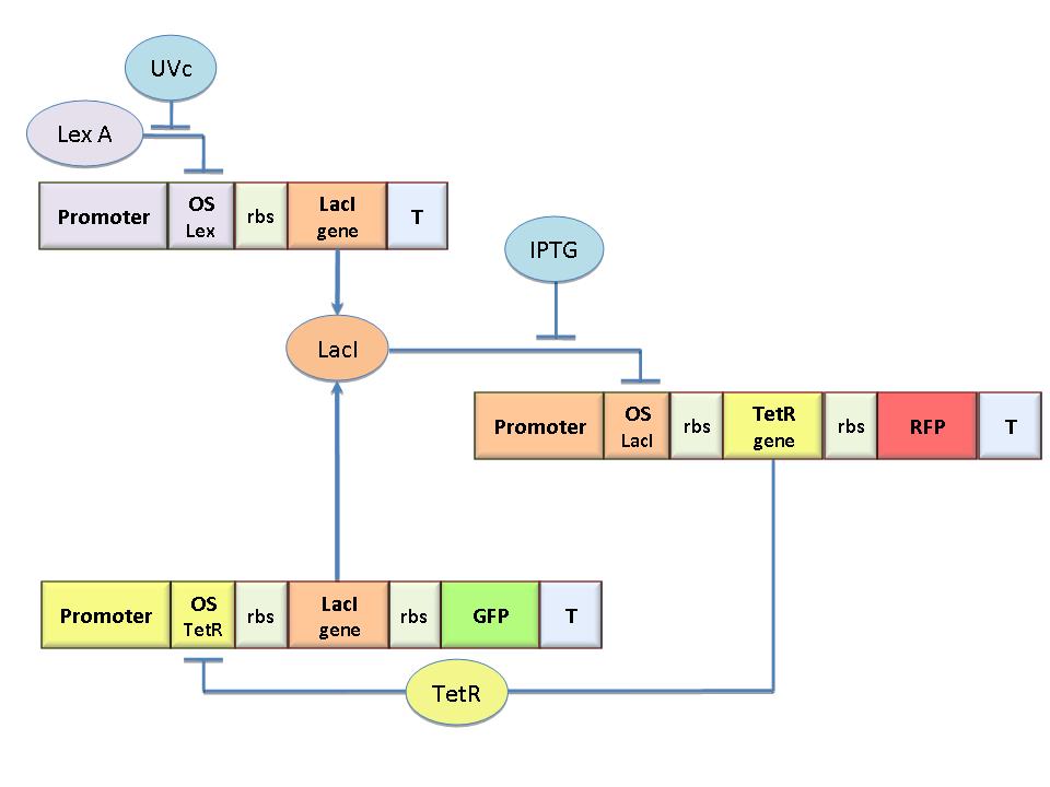
The circuit in Figure 1 can be modeled with the following equations:
Where:
In the model we distinguish between protein binded to repressor ()and protein free, not binded to repressor (), in this case repressor is represented by IPTG. Knowing that and the law of mass action is possible write where we can replace represents the entry of IPTG inside the cell. The same thing can be done even for LexA obtaining where represents the UV radiation.Placing:
 "
"


