Team:Bologna/Modeling
From 2008.igem.org
| HOME | PROJECT | TEAM | SUBMITTED PARTS | MODELING | WETLAB | LAB-BOOK | BIOSAFETY AND PROTOCOLS |
|---|
Contents |
Mathematical Model of the Flip-Flop genetic circuit
Model definition
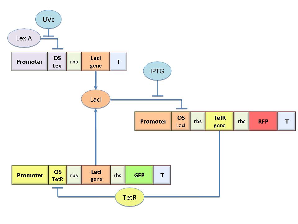
The genetic circuit in Figure 1 works as a Flip-Flop, which can switch between two different states according to the external stimuli (latch JK).
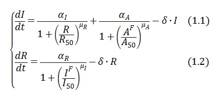
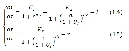
The circuit behaviour can be modeled by the following equations:
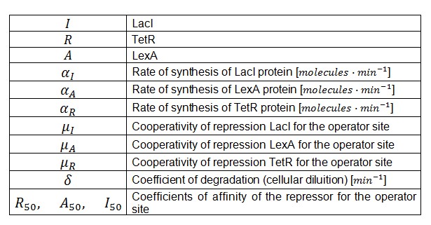
Symbols and parameters are defined in Table 1:
- A common motif in repressor proteins is the presence of a dimeric nucleotide binding site. In accordance to this general structure the cooperativity coefficients () were assumed equal to 2.
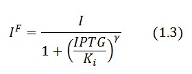
In the model we distinguish between LacI protein binded to repressor IPTG ![]() and protein free
and protein free ![]() .
.
Since ![]() and considering the law of mass action
and considering the law of mass action ![]() we can write:
we can write:
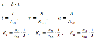
Adimensional equations
The equations (1.1) and (1.2) were modified to an adimensional form:
where:
Equibrium conditions
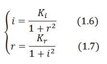
At equilibrium and in absence of stimuli, the adimensional concentrations of LacI (i) and TetR (r) are related by the equation:
To obtain these equations the second term in equation (1.5)was ignored (). This is justified by the high binding constant of LexA for its operator, and the consequent low production of LacI (see Figure 1).
Stability analysis
Assuming as starting condition the LacION state (Figure 1) its stability is guaranteed if the adimensional concentration of LacI is higher than 1 (Figure 2).
In the limit of (), equation (1.7) simplifies:
Experimental identification
The MAVs were identified comparing the experimental response of the genetic circuits in Figure
 "
"


