Team:EPF-Lausanne/Project
From 2008.igem.org
(→The rule) |
(→The rule) |
||
| Line 41: | Line 41: | ||
Also depending on the number of inputs, the rule determines which response the system gives to the inputs it receives, this response corresponding to the future genetic circuit that we will implement. | Also depending on the number of inputs, the rule determines which response the system gives to the inputs it receives, this response corresponding to the future genetic circuit that we will implement. | ||
| - | First, we tried to simulate a two-colors system into this network (fig. 1), which allows only a few rules, given the fact that the maximum number of inputs is two. Going through all the rules, we obtained only little interesting | + | First, we tried to simulate a two-colors system into this network (fig. 1), which allows only a few rules, given the fact that the maximum number of inputs is two. Going through all the rules, we obtained only little interesting |
| + | [[Image:Connectivity1top.jpg]] | ||
[[Image:5050.jpg|200px]] | [[Image:5050.jpg|200px]] | ||
Then, we tried to simulate a two-colors system into this network (fig. 2), which allows more rules given the fact that the maximum number of inputs is now three. Going through all the rules, we obtained more interesting patterns. We finally decided to produce this pattern (fig. 3) and selected this final network. | Then, we tried to simulate a two-colors system into this network (fig. 2), which allows more rules given the fact that the maximum number of inputs is now three. Going through all the rules, we obtained more interesting patterns. We finally decided to produce this pattern (fig. 3) and selected this final network. | ||
| + | [[Image:Connectivity2.jpg]] | ||
[[Image:Fullpatches_1010.jpg|200px]] | [[Image:Fullpatches_1010.jpg|200px]] | ||
[[Image:Triangles.jpg|200px]] | [[Image:Triangles.jpg|200px]] | ||
Revision as of 14:42, 27 October 2008
| Home | The Team | The Project | Parts | 2-step PCR | Microfluidics | Modeling | Notebook |
|---|
Contents |
Genetic network generating spatial patterns through cell-cell communication and controlled information processing
Abstract
Biological systems are unique in their ability to combine information and energy to generate complex entities. Genetically encoded networks drive many of these patterning processes. Furthermore, developmental studies have highlighted the importance of gradient formation and cell-cell communication for the generation of cellular patterns in the early stages of life. It has been shown that simple networks can form both static and dynamic patterns. Nonetheless, a system whose pattern formation is dependent on combinations of multiple signals has yet to be demonstrated. Here we address this question by designing a network, involving two different quorum-sensing based signaling mechanisms. Upon introduction in E.coli, the system can sense the relative amounts of two input molecules. Using a pre-define set of rules which was selected on its ability to generate spatial patterns, the cell can then express its final state by emitting red or green fluorescence and transmit its state to its neighbors.

General Introduction and Context
Quorum sensing has been a wide-spread interest of synthetic biology in recent years. The ability to have populations of cell communicate in such a way that they either relay information or create specific patterns in culture is one which has been used in several studies (cite...). Some have relied on two different cell populations (predator-prey ref. for example) to engineer in vitro behaviors previously inexisting in the bacteria.
The idea of the project is to build a system which uses two different quorum sensing sets of molecules that make the cell able to integrate three different levels of signal, and emit a different response, by producing a given fluorescent protein and a quorum sensing molecule.
Our project uses a single population of cells, which all contain the same genetic information. Thus, the different behavior of the sub-populations will only be dictated by neighbouring sub-populations. We also take advantage of the high-level engineering competences found in our Institute (EPFL) by using microfluidic devices in order to culture the cells in an ordered and controllable manner. These devices are custom-made for the project and consist in PDMS chips in which we design an array of miniature chambers to culture cells, linked to each other with a network of ducts. This enables us to culture sub-populations of our cells in contact with each other in an environment of medium, and to make these communicate with each other in a controlled manner for signal propagations.
Our microfluidic devices are also used in a side-project in order to characterise molecules and cell behavior in their contact.
Biomedical application
We may be able to apply this idea to automated system of drug producing for personal medicine. In such a system, you just put a sample of blood in the first column of a microfluidics chip, then engineered cells in the wells detect some solutes, antibodies, and so on, and produce a signal given what they detect. Then the signal is integrated along the chip and when it reaches the last column, the engineered cell put in the wells are able to produce drugs responding to diseases detected along the chip.
As you would certainly suppose, we will not be able to engineer all the cell types to aim this goal in one summer, but we want through our project to make a few first steps to make such a system feasable in the future.
Prehistory of the project
The very first step of our project was to determine the general parameters of our project. With the help of very simple Matlab files, we went through the different possibilities for each parameter. Our goal was to find the most interesting patterns, understanding interesting as complex patterns made by a simple system. We will now detail our choice for each of the parameters. Here are the three parameters :
The number of colors
As said before, we wanted to get the simplest system, so we started with only two colors - therefore two quorum sensing systems.
The number of inputs
As we were trying to sense a threshold, this was an really important step of our reflexion. We tried with two different inputs, before going to three different inputs.
The connectivity
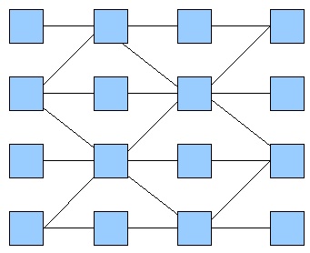
This part of the reflexion was tightly linked with the previous - number of inputs. Another constraint was, that for microfluidics purposes, the system could not have crosslinking between channels linking the wells.
The rule
Also depending on the number of inputs, the rule determines which response the system gives to the inputs it receives, this response corresponding to the future genetic circuit that we will implement.
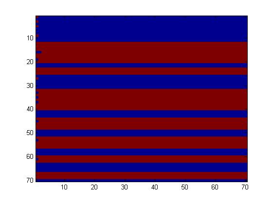
First, we tried to simulate a two-colors system into this network (fig. 1), which allows only a few rules, given the fact that the maximum number of inputs is two. Going through all the rules, we obtained only little interesting
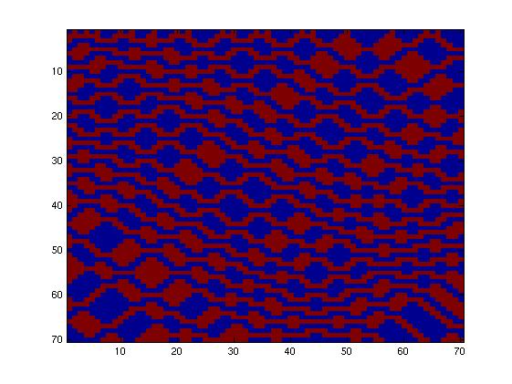
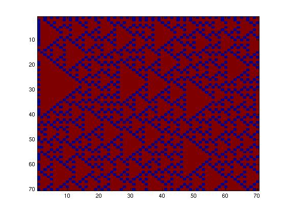
Then, we tried to simulate a two-colors system into this network (fig. 2), which allows more rules given the fact that the maximum number of inputs is now three. Going through all the rules, we obtained more interesting patterns. We finally decided to produce this pattern (fig. 3) and selected this final network.
We had now to implement the genetic circuit implementing the rule and go through modeling of higher complexity to determine the stability of the system.
Project Details
The genetic circuit which will be implemented in the cells is the following :
This genetic circuit must give this following pattern :
Our system is the combination between a new plasmid and a pre-existing system ("A synthetic multicellular system for programmed pattern formation", from Ron Weiss et al., Nature, vol.434, April 2005) which detect different level of the luxI quorum sensing molecule and give a specific response according to the concentration received. As shown on the previous genetic circuit, we will add the RhlI molecule after the GFP, Rhl being our second quorum sensing molecule used. In addition to the two Ron Weiss system plasmids, we have to build an extra plasmid with the second part of the genetic circuit. We will add an extra copy of the LacIm gene so that we can test it idenpendently from the Ron Weiss system.
Here is the scheme of the plasmid with the Registry of Standard Parts references for each Biobrick we use.

!!!Here should come the definitive cloning scheme (order in which the parts have been cloned together).
The microfluidic devices built this summer and fall come in two kinds. The design for the first, the MITOMI devices allowing for characterisation of molecules, is the following :
add picture!!
Microfluidic chips for cell culture and quorum sensing have the following design :
add picture!!
Experiments
CF the general plan we agreed on for the contents of this part.
Results
CF the general plan we agreed on for the contents of this part.
 "
"


