Switch Circuit
Introduction
Many biological applications require a pulse mechanism that enables on the one hand a fast production and high accumulation of specific protein at one time and on the other hand a fast elimination of this protein after a period of time has passed. Pulse generators that turn on and off protein production are essential parts of engineered genetic circuits and allow the synthetic biologist to control timed expression of the protein of interest. It is obvious that a robust pulse generator is essential for our approach to the minimal genome, since we are planning to express a restriction enzyme in a brief pulse that is short enough to cause sublethal damage to the cells’ genome but on the other hand long enough to allow the restriction enzyme to leave a lasting impression on the genome. It is obvious that the ideal duration of restriction enzyme expression pulse has to be determined empirically by inducing expression of the restriction enzyme for different durations and at the same time monitoring the survival rate of the cells. Pulse generators based on a feed-forward motif have been described previously and are considered superior since they require only one inducer and automatically terminate expression of the protein after a certain time has passed, however, they are parameter-sensitive and difficult to construct. For our approach this type of pulse generator is of little use, since change of the duration of the pulse requires extensive modification to the constructs holding the pulse generator. We have therefore devised a very simple, but effective pulse generator, which turns on protein expression upon induction with IPTG or lactose and turns off protein expression by induction with tetracycline. This pulse generator functions as a switch and allows the synthetic biologist to turn expression of a gene on and off at will for durations specified by the experimenter rather that by parameters of the construct. Our pulse generator acts on promotors, which contain the lac repressor binding motif. Those promotors are used almost universally for recombinant protein expression such as in the [http://www.merckbiosciences.com/g.asp?f=NVG/pETtable.html pET vectors] of the T7 expression system (1-3) and can be subjected to control by our pulse generator without further modification.
General layout of the pulse generator
The basic idea for the pulse generator was to use the lac repressor to control the start of expression and then use a second protein under control of a different promotor, which in turn would shut down expression by binding tightly to a motif contained inside the lac repressor binding site after induction of it’s promotor with a second inducer. While there are numerous proteins, which bind tightly to specific DNA sequences and while it is even possible to engineer these proteins to bind to a DNA sequence of choice (4-7), we decided to use the IS lac repressor mutant, which binds to the lac repressor binding site like the wild type but does not lose affinity for the binding site upon IPTG or lactose induction (8). Since expression of the mutant lacI has to be tightly controlled to avoid repression of lac-controlled gene expression despite presence of inducer, it was decided to put it under control of the tet repressor (9, 10). The pulse generator consists of two parts, a constitutively active tetR generator (unlike in the case of the lac repressor, which is expressed under control of it’s own promotor, ‘’E. coli’’ does not produce tet repressor) and a lacI IS mutant gene under the control of the tet repressor. The constitutively active tetR generator supplies the tetR repressor, which binds to the repressor binding site in front of the lacI IS gene and releases the binding site upon induction with tetracycline. Induction with tetracycline leads to expression of the lacI IS mutant and this protein binds to the lac repressor binding site in front of the activated gene of interest despite presence of lactose or IPTG activator. With this system, IPTG induction initiates expression of the protein of interest while tetracycline induction rapidly terminates the expression of the protein.
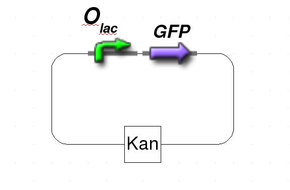
Figure 1: Schematic representation of the target plasmid.
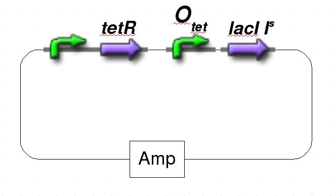
Figure 2: Schematic representation of the pulse generator.
Design of the lacI IS mutants
Since the discovery of the lac repressor over 40 years ago (11), it has been subjected to extensive genetic studies, which have identified numerous mutants with different defects in activity (8, 12-25). The determination of the atomic structure of the lac repressor by itself (26) and in complex with IPTG (27) by x-ray crystallography furthered the understanding of repressor activity on the molecular level and allowed to assign mutations to different functional regions of the molecule. Mutations in several regions of the lac repressor can lead to the lacI IS phenotype: Mutations at the N-terminal domain of the core, mutations of the dimerization interface and mutations of the residues, which establish the IPTG contact. We decided to create lacI IS mutants by mutation of two residues, which form part of the IPTG binding site: R197 and T276.
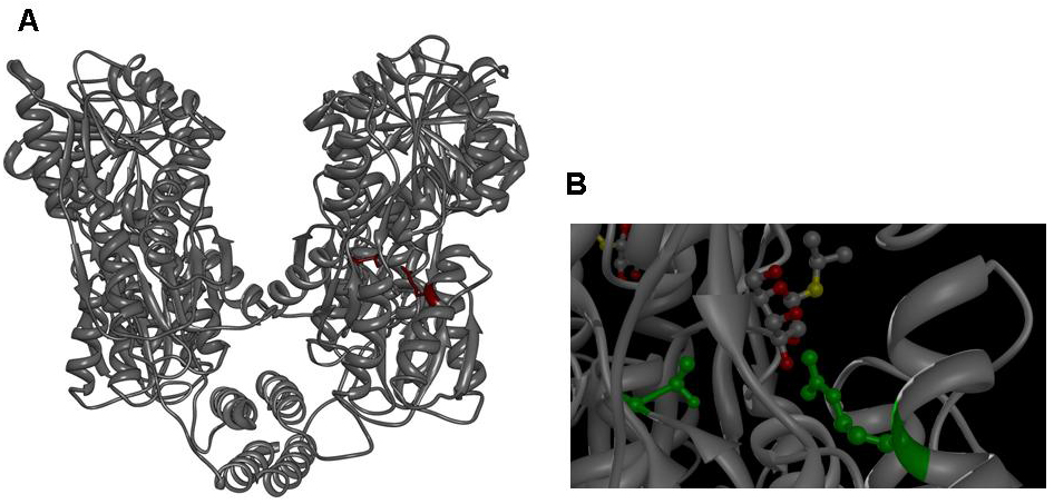
Figure 3: A Lac repressor tetramer, residues R197 and T276 are shown in red. B IPTG bound to the inducer binding site of the lac repressor, residues R197 and T276 are shown in green. Molecular graphics was generated from coordinate set [http://www.rcsb.org/pdb/explore.do?structureId=1LBH 1lbh] (27) using [http://www.cgl.ucsf.edu/chimera/ UCSF Chimera].
We are not aware of quantitative studies that detail the strength of repression with respect to different mutations (in one genetic study (8) a repressor strength of >200 has been determined for numerous IS mutants including mutations of R197 and T276) or with respect to the combination between different mutations and we therefore set out to replace either residue with alanine or phenylalanine and in addition we constructed double mutants with all combinations of the two mutations. Our set of lacI IS mutations therefore comprises eight different mutants: R197A; R197F; T276A; T276F; R197A T276A; R197A T276F; R197F T276A; R197F T276F
Estimate of lacI IS repressor strength
In order to characterize the lacI IS mutants generated – especially with respect to the double mutants – we performed a series of simple genetic experiments, which would allow us to identify promising mutations and reject mutations that allow significant induction at IPTG concentrations regularly used for induction (usually between 0.1mM and 1mM). Ideally, the experiment would link repression of a lac inducible gene to a marked change in cell growth or morphology. We decided to use ribosome modulation factor (RMF) in one series of experiments and fluorescent proteins in another series as an indicator of lac repressor activity.
Ribosome modulation factor (RMF) experiments
Ribosome modulation factor (RMF, Uniprot [http://www.uniprot.org/uniprot/P0AFW2 P0AFW2]) is a small protein, which is found in many bacteria. RMF is expressed when bacterial cultures reach the stationary phase (28, 29) and terminates protein synthesis efficiently by binding to ribosomes. Biochemical studies have shown that expression of RMF leads to dimerization of ribosomes (the bacterial 70S ribosomes form a complex with a sedimentation velocity of 100S) and chemical crosslinking studies elucidated that RMF binds to the peptidyl transferase center (30, 31). Since expression of RMF reversibly terminates protein expression and thereby stops bacterial growth we used RMF to determine the extent of lac repression by mutant lacI repressors. Since RMF is useful for several applications in synthetic biology, we decided to provide it as BioBrick [http://partsregistry.org/wiki/index.php?title=Part:BBa_K142040 K142040]. We amplified RMF from pET28a-RMF using forward primer 5'-cgcggaattcgcggccgcttctagatgaagagacaaaaacgagatcgcctgg and reverse primer 5'-cgcgctgcagcggccgctactagtattattaggccattactaccctgtccgc and subcloned it into pSB1A7 using the BioBrick restriction sites.

Figure 4: A 1.5% agarose gel with M: marker ([http://www.fermentas.com/catalog/electrophoresis/generulers.htm Fermentas] 100bp DNA ladder plus); pSB1A7: vector pSB1A7 digested with XbaI and SpeI according to [http://www.neb.com NEB] manual; RMF: PCR product of RMF amplified from DH5-alpha genomic DNA using forward primer 5'-cgcggaattcgcggccgcttctagatgaagagacaaaaacgagatcgcctgg and reverse primer 5'-cgcgctgcagcggccgctactagtattattaggccattactaccctgtccgc; reaction setup was 35ul water, 10ul [http://www.finnzymes.com/highperformancepcr.html Finnzyme] Phusion HF buffer, 1ul 10mM dNTPs, 1ul 25uM forward primer, 1ul 25uM reverse primer, 0.5ul DH5-alpha genomic DNA, 0.5ul [http://www.finnzymes.com/highperformancepcr.html Finnzyme] Phusion Hot-start polymerase; thermocycler program was 98C for 3min, cycle start: 98C for 10s, 55C for 30s, 72C for 10s, cycle end, 35 repeats, 72C for 30min, 4C hold; the PCR product was restriction digested with XbaI and SpeI and purified using Qiagen Qiaquick PCR purification kit; ligation: ligation of XbaI/SpeI linearized pSB1A7 with RMF insert. B 2% agarose gel of test digests (XbaI/SpeI; according to [http://www.neb.com NEB] manual) of pSB1A7-RMF. Six colonies were used for overnight cultures and test digested; colonies were designated R1, R2, R3, R4, R5, R6. Only R2, R4, R5 and R6 contain the insert (arrow), However, sequencing of the insert showed that an unidentified piece of DNA had been amplified and cloned into the vector.
In order to perform this genetic experiment, we amplified RMF from E. coli strain DH5-alpha DNA using forward primer 5’-cgcggatccgaaaacctgtattttcagggcaagagac
aaaaacgagatcgcctg and reverse primer 5’-ccgctcgagttattaggccattactaccctgtcc (reaction setup was 35ul water, 10ul [http://www.finnzymes.com/highperformancepcr.html Finnzyme] Phusion HF buffer, 1ul 10mM dNTPs, 1ul 25uM forward primer, 1ul 25uM reverse primer, 0.5ul DH5-alpha genomic DNA, 0.5ul [http://www.finnzymes.com/highperformancepcr.html Finnzyme] Phusion Hot-start polymerase; thermocycler program was 98C for 3min, cycle start: 98C for 10s, 55C for 30s, 72C for 10s, cycle end, 35 repeats, 72C for 30min, 4C hold). We subsequently digested the PCR product with XhoI and BamHI and subcloned it into the pET28a vector ([http://www.merckbiosciences.com/g.asp?f=NVG/pETtable.html Novagen]) multiple cloning site. In order to determine whether the construct is expressed correctly and in order to verify the physiological reaction of E. coli cells to expression of RMF, we electroporated pET28a-RMF into BL21 DE3 cells (which hold a T7 polymerase gene on their genome and are therefore able to express genes under the T7 promotor) and plated the cells on LB-agar plates supplemented with kanamycin. In order to verify the termination of growth after induction of RMF expression, we grew cells holding the plasmid and found that growth terminates rapidly upon induction. We prepared ribosomes from induced cells and measured their sedimentation velocity. Induced cells contain two poulations of ribosomes, one with a sedimentation velocity of 70S (suggesting monomeric ribosomes) and the other with a sedimentation velocity of 100S (suggesting dimers). Analysis of the different fractions by negative-stain transmission electron microscopy confirmed that both fractions consist of ribosomes although both of them appear monomeric in the electron microscope (probably the interaction is very weak and breaks up upon adsorption onto the carbon grid; an image of dimeric ribosomes seen in the electron microscope after the sample was treated with substantial amounts of glutaraldehyde has been published previously (31)). The two populations of ribosomes are equally found in uninduced cells, which have progressed into the stationary phase of growth.
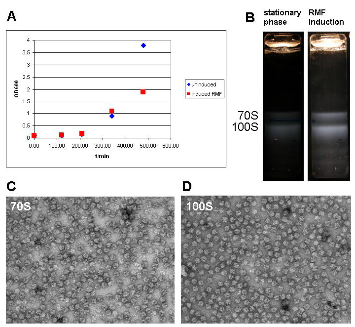
Figure 5: A Growth curve of BL21 DE3 cells holding the pET28a-RMF plasmid without induction (uninduced) and after induction after 5 hours. Cells were grown in 1l of medium in 5l baffled flasks (37C, 95rpm) and induced once they had reached the exponential phase. B Ribosome profile of cells in the stationary phase and after RMF induction. Cells were harvested by centrifugation (Sorvall SLC-6000 rotor, 7200rpm, 10min, 4C) and disrupted in a cell disruptor (Constant systems). The lysate was cleared at 13000 rpm in a SLA-1500 rotor in a Sorvall refrigerated centrifuge. Supernatant was collected and layered on top of a 30% sucrose solution (50mM HEPES-KOH pH 7.6; 100mM KCl; 10mM MgCl2; 1mM DTT). After centrifugation at 50000rpm for 20 hours at 4C in the preparative ultracentrifuge using a Ti70 rotor ([http://www.beckmancoulter.com Beckman Coulter]) the supernatant was decanted and the pellet resuspended in ribosome buffer (50mM HEPES-KOH pH 7.6; 100mM KCl; 10mM MgCl2; 1mM DTT). The resuspended ribosomes were layered on top of a 10 to 40% (w/w) sucrose gradient, which was centrifuged in the SW32 swing rotor at 28000 rpm for 7 hours. Ribosome bands were visualized by ([http://en.wikipedia.org/wiki/Tyndall_effect light scattering]) and photographed with a Nikon D80 SLR. C and D Electron micrographs of the 70S and 100S fraction show monomeric ribosomes in both fractions as the only macromolecular constituent. Ribosome samples were diluted to OD260 = 1. 7ul of ribosome solution was added to a glow discharged carbon grid ([http://www.quantifoil.com Quantifoil]) and stained with uranyl acetate according to standard protocol (1min sample adsorption, three times washing with 1% uranyl acetate solution by floatation). Samples were imaged with a [http://www.fei.com FEI] Morgagni 268 transmission electron microscope with tungsten emitter at an acceleration voltage of 100kV; 30000x magnification and recorded with a post column Gatan CCD camera.
We took advantage of the constitutive lac expression cassette in the pET28a vector and used PCR-based site-directed mutagenesis to introduce lacI IS muations into the lacI generator of the pET28a-RMF vector. In order to perform this mutagenesis, we used forward primers
R197F forward 5’-CGGCGCGTCTGTTTCTGGCTGGCTG
R197A forward 5’-CGGCGCGTCTGGCGCTGGCTGGCTG
T276F forward 5’-GGATACGACGATTTTGAAGACAGCTC
T276A forward 5’-GGATACGACGATGCGGAAGACAGCTC
and reverse primers
R197F reverse 5’-CAGCCAGCCAGAAACAGACGCGCCG
R197A reverse 5’-CAGCCAGCCAGCGCCAGACGCGCCG
T276F reverse 5’-GAGCTGTCTTCAAAATCGTCGTATCC
T276A reverse 5’-GAGCTGTCTTCCGCATCGTCGTATCC
to introduce either a single mutation or double mutations. PCR was performed using vector pET28a-RMF as template. Transformation into BL21 DE3 cells yielded numerous colonies. For each construct eight colonies were streaked out on LB-agar supplemented with kanamycin. In order to test the repressor strength we streaked each of these clones onto plates of progressively higher IPTG concentration and monitored the growth. As a control, the unmodified vector was streaked out on plates with and without IPTG and IPTG toxicity was assayed by streaking cells holding an empty pET28a vector onto a 10mM IPTG plate. With the mutated lacI IS as a major source of repressor we assumed that cells would be viable even at high IPTG concentration, since expression of RMF would be repressed by the mutated, IPTG-insensitive lacI. Indeed, cells grew normally up to an IPTG concentration of 10mM, which is 10- to 100-fold the concentration usually used for induction. While empty pET28a vector is not toxic for cells even at 10mM IPTG, pET28a-RMF wild type vector prevents growth even at low concentrations of IPTG.
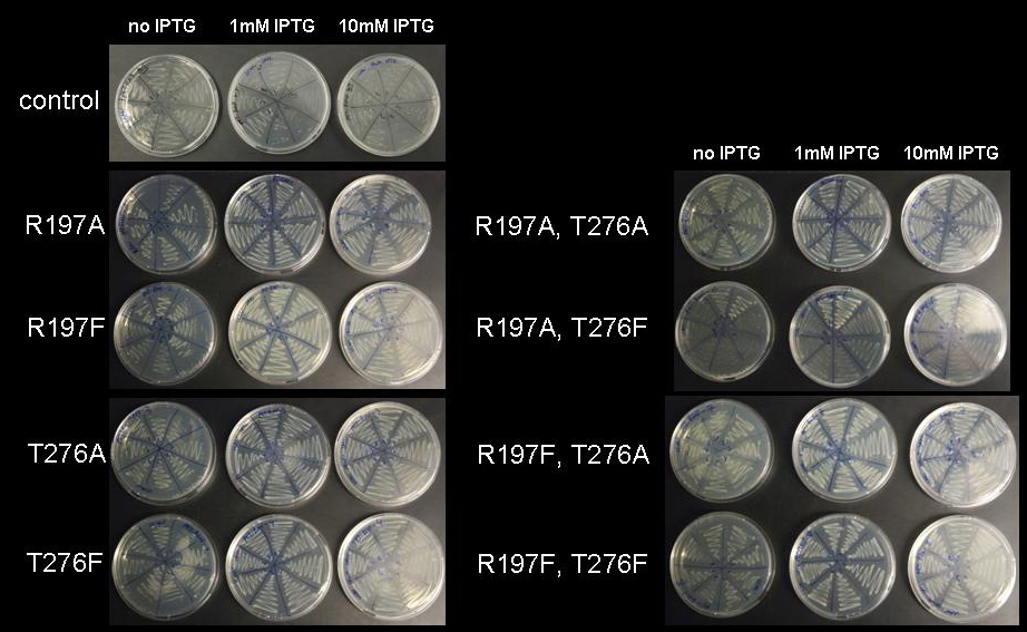
Figure 6: Cell viability at increasing IPTG concentration. BL21 DE3 cells holding the pET28a-RMF plasmid with mutations R197A; R197F; T276A; T276F; R197A T276A; R197A T276F; R197F T276A; R197F T276F were plated on LB-agar with kanamycin without IPTG, with 1mM IPTG and with 10mM IPTG
Therefore we can speculate that repression by all lacI mutants generated is strong enough to silence promotors with lac repressor binding site even at unusually high IPTG concentrations.
(However, there is one caveat: One important issue with the experiment is that, we have not been able to obtain sequences of the generated mutants before closing of the Wiki. Therefore it is important to note that the repression shown might stem from mutations in the RMF gene or the T7 promotor which abolish expression of RMF altogether and allow the cell to grow even at high concentrations of inducer while giving the incorrect impression that the lacI IS mutant generated strongly represses expression of RMF. While we can not rule out this possibility without sequencing data of the T7 promotor and the RMF gene, we think that it is unlikely that we have generated solely mutations of RMF. Since PCR is considerably more error prone than plasmid propagation inside the cell, the mutation of RMF would more likely have taken place during the amplification process. With [http://www.finnzymes.com/highperformancepcr.html Finnzyme] Phusion polymerase we have used one of the least error-prone polymerases available, which reduces the chance of generating mutants in the promotor and RMF gene region substantially. Since we have used the T7 expression system (1-3), which shows extremely low levels of leaky expression, and since we have plated the cells on plates containing no lactose or IPTG after transformation, we assume that no selection in favor of inactive RMF mutants has taken place in the first step. The potential library of mutants inadvertently generated by PCR therefore would not have been selected towards nonfunctional expression of RMF before colonies were picked and streaked onto plates containing IPTG. Controls transformed with the regular pET28a-RMF show no growth even at moderate IPTG concentrations; hence the original plasmid shows strong expression of RMF upon induction.)
Fluorescent protein experiments
While the estimation of repressor strength of the lacI IS mutants in the genetic experiment with the pET28a-RMF mutants has yielded some qualitative data suggesting that all mutants repress expression of lac controlled genes even at high IPTG concentrations, we attempted to quantify the repressor strength of different lacI IS mutants. We cloned the constitutive lacI expression cassette, which had been constructed by the iGEM team of ETH Zurich in 2007, (BioBrick [http://partsregistry.org/wiki/index.php?title=Part:BBa_I739002 BBa_I739002]) behind one of several lac-controlled fluorescent protein generators (BioBricks [http://partsregistry.org/Part:BBa_I763004 I763004], [http://partsregistry.org/Part:BBa_J04430 J04430], [http://partsregistry.org/Part:BBa_I13601 I13601], [http://partsregistry.org/Part:BBa_J5526 J5526] ). The order of the assembly was directed by the intention to minimize readthrough of the RNA polymerase from the constitutive expression cassette into the lac-controlled reporter gene. Placing the lacI generator behind the fluorescent protein generator was assumed to help decreasing the background of leaky reporter protein expression. The constructs holding GFP and RFP were selected for site-directed mutagenesis, since they are easily detectable with the filter set of our plate reader and – in the case of RFP – even detectable by eye. Site directed mutagenensis was carried out by PCR using forward primers
R197F forward 5’-CGGCGCGTCTGTTTCTGGCTGGCTG
R197A forward 5’-CGGCGCGTCTGGCGCTGGCTGGCTG
T276F forward 5’-GGATACGACGATTTTGAAGACAGCTC
T276A forward 5’-GGATACGACGATGCGGAAGACAGCTC
and reverse primers
R197F reverse 5’-CAGCCAGCCAGAAACAGACGCGCCG
R197A reverse 5’-CAGCCAGCCAGCGCCAGACGCGCCG
T276F reverse 5’-GAGCTGTCTTCAAAATCGTCGTATCC
T276A reverse 5’-GAGCTGTCTTCCGCATCGTCGTATCC
to achieve single mutations R197A; R197F; T276A; T276F and double mutants R197A T276A; R197A T276F; R197F T276A; R197F T276F. DpnI digest was used to dispose of the template and samples were electroporated into DH5-alpha cells. However, at time of closing of the Wiki measurements of fluorescence at different concentrations of inducer had not been performed yet.
Assembly of the Pulse generator
We decided to assemble the pulse generator from the constitutive tetR expression cassette [http://partsregistry.org/wiki/index.php?title=Part:BBa_I739001 I739001] and the tet-controlled lacI generator [http://partsregistry.org/Part:BBa_I763026 I763026]. According to the information available at the time we started cloning, we assumed that cloning the tetR generator behind the lacI expression cassette and subsequent site-directed mutagenesis would be sufficient to construct the pulse generator. However, when the Caltech team sequenced BioBrick [http://partsregistry.org/Part:BBa_I763026 I763026], they found that it did not contain a promotor, but rather started with the ribosome binding site. Therefore, we revised our cloning strategy and tried two different approaches. We firstly cloned the lacI generator behind the tet-controlled promotor [http://partsregistry.org/Part:BBa_R0040 R0040] in order to assemble a part that has the deposited sequence of [http://partsregistry.org/Part:BBa_I763026 I763026]. In the attempt to try a different approach, we at the same time cloned the tetR-generator behind the promotorless lacI generator. In the next step, we cloned the tetR expression cassette behind the lacI generator with tet-controlled promotor and subjected the assembly to site-directed mutagenesis.
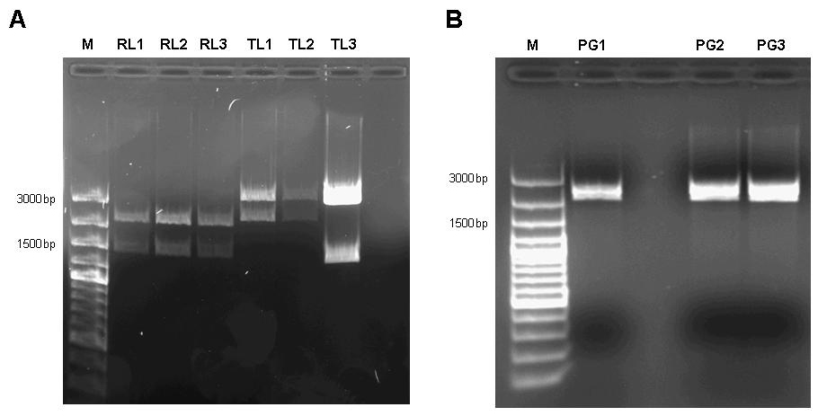
Figure 7: A 1% agarose gel of XbaI/PstI test digests of plasmids holding the lac generator [http://partsregistry.org/Part:BBa_I763026 I763026] behind the tet-controlled promotor [http://partsregistry.org/Part:BBa_R0040 R0040] (RL1, RL2, RL3) and of XbaI/PstI test digests of plasmids holding the constitutive tetR expression cassette [http://partsregistry.org/wiki/index.php?title=Part:BBa_I739001 I739001] behind the promotorless lacI generator [http://partsregistry.org/Part:BBa_I763026 I763026] (TL1, TL2, TL3). The insert size agrees with the expected size in the case of RL1, RL2, RL3, TL1, TL2. TL3 apparently religated despite dephosphorylation treatment with alkaline phosphatase (CIP) and does not contain the aforementioned tetR expression cassette. B 1% agarose gel of XbaI/SpeI test digests of assembled pulse generator precursor containing BioBricks [http://partsregistry.org/Part:BBa_R0040 R0040] [http://partsregistry.org/Part:BBa_I763026 I763026] [http://partsregistry.org/wiki/index.php?title=Part:BBa_I739001 I739001]. Insert size conforms with the expected size in all cases.
Unfortunately only one of the eight mutagenensis expriments by PCR had worked by end of the Wiki deadline. However, since all mutants had shown considerable repressor strength in the previous genetic experiments, we assumed it safe to continue experimentation on this particular construct.
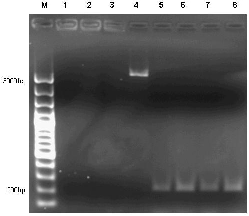
Figure 8: 1% agarose gel of PCR products of site directed mutagenesis of the final pulse generator assembly consisting of [http://partsregistry.org/Part:BBa_R0040 R0040] [http://partsregistry.org/Part:BBa_I763026 I763026] [http://partsregistry.org/wiki/index.php?title=Part:BBa_I739001 I739001]. Template DNA of the pulse generator precursor [http://partsregistry.org/Part:BBa_R0040 R0040] [http://partsregistry.org/Part:BBa_I763026 I763026] [http://partsregistry.org/wiki/index.php?title=Part:BBa_I739001 I739001] was amplified by PCR in eight different reactions using primers 276F forward 5’-GGATACGACGATTTTGAAGACAGCTC; T276A forward 5’-GGATACGACGATGCGGAAGACAGCTC; R197F reverse 5’-CAGCCAGCCAGAAACAGACGCGCCG ; R197A reverse 5’-CAGCCAGCCAGCGCCAGACGCGCCG; T276F reverse 5’-GAGCTGTCTTCAAAATCGTCGTATCC ; T276A reverse 5’-GAGCTGTCTTCCGCATCGTCGTATCC in combinations as to produce the desired mutations R197A; R197F; T276A; T276F and double mutants R197A T276A; R197A T276F; R197F T276A; R197F T276F. Each reaction setup contained 35ul water, 10ul [http://www.finnzymes.com/highperformancepcr.html Finnzyme] Phusion polymerase HF buffer, 1ul 10mM dNTPs, 5ul primer mix (primers at 100ng/ul), 1ul of diluted DNA template (approximate concentration after dilution 10ng/ul), 0.5ul [http://www.finnzymes.com/highperformancepcr.html Finnzyme] Phusion Hot Start polymerase. The reaction was run with the following thermocycler program: 95C for 30sec, cycle start, 95C 30 sec, 55C 1min, 72C 2min, cycle end, 18 repeats, 72C for 30min, 4C hold. After the PCR reaction had gone to completion, 10ul of 50mM MgCl2 were added to each reaction tube and the contents were thoroughly mixed. 1ul of DpnI (equivalent to 20 units) were added to each tube and the contents were thoroughly mixed. The reaction was incubated in the thermocycler following the program: 37C for 120min, 4C hold. Samples were purified with Qiaquick PCR purification kit and separated on a 1% agarose gel stained with ethidium bromide. It is obvious that the PCR reaction failed in all cases except for reaction number 4, where a small amount of product was generated. Interestingly, amplification between the primers – as evidenced by the bands slightly above 200bp in lanes 5 to 8 – nevertheless took place in the double mutant setup.
In addition, since all assembly intermediates are potentially useful BioBricks for genetic circuit engineering, we decided to subject both, the lacI gene by itself (as contained in BioBrick [http://partsregistry.org/Part:BBa_C0012 C0012]) and the, as it later turned out promotorless, Biobrick [http://partsregistry.org/Part:BBa_I763026 I763026] to site-directed mutagenesis to produce a set of lacI IS mutants.
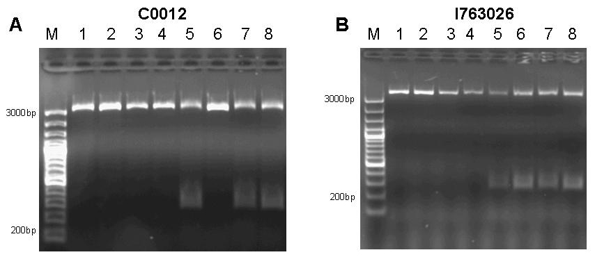
Figure 9: A 1% agarose gel of PCR products of site directed mutagenesis of C0012. Template DNA of BioBrick [http://partsregistry.org/Part:BBa_C0012 C0012] was amplified by PCR in eight different reactions using primers 276F forward 5’-GGATACGACGATTTTGAAGACAGCTC; T276A forward 5’-GGATACGACGATGCGGAAGACAGCTC; R197F reverse 5’-CAGCCAGCCAGAAACAGACGCGCCG ; R197A reverse 5’-CAGCCAGCCAGCGCCAGACGCGCCG; T276F reverse 5’-GAGCTGTCTTCAAAATCGTCGTATCC ; T276A reverse 5’-GAGCTGTCTTCCGCATCGTCGTATCC in combinations as to produce the desired mutations R197A; R197F; T276A; T276F and double mutants R197A T276A; R197A T276F; R197F T276A; R197F T276F. Each reaction setup contained 35ul water, 10ul [http://www.finnzymes.com/highperformancepcr.html Finnzyme] Phusion polymerase HF buffer, 1ul 10mM dNTPs, 5ul primer mix (primers at 100ng/ul), 1ul of diluted DNA template (approximate concentration after dilution 10ng/ul), 0.5ul [http://www.finnzymes.com/highperformancepcr.html Finnzyme] Phusion Hot Start polymerase. The reaction was run with the following thermocycler program: 95C for 30sec, cycle start, 95C 30 sec, 55C 1min, 72C 2min, cycle end, 18 repeats, 72C for 30min, 4C hold. After the PCR reaction had gone to completion, 10ul of 50mM MgCl2 were added to each reaction tube and the contents were thoroughly mixed. 1ul of DpnI (equivalent to 20 units) were added to each tube and the contents were thoroughly mixed. The reaction was incubated in the thermocycler following the program: 37C for 120min, 4C hold. Samples were purified with Qiaquick PCR purification kit and separated on a 1% agarose gel stained with ethidium bromide. The additional bands at ~300bp visible in lanes 5, 7 and 8 are PCR products that span the distance between the two sets of primers of the double mutation. B 1% agarose gel of PCR products of site directed mutagenesis of [http://partsregistry.org/Part:BBa_I763026 I763026]. Template DNA of BioBrick [http://partsregistry.org/Part:BBa_I763026 I763026] was amplified by PCR in eight different reactions using primers 276F forward 5’-GGATACGACGATTTTGAAGACAGCTC; T276A forward 5’-GGATACGACGATGCGGAAGACAGCTC; R197F reverse 5’-CAGCCAGCCAGAAACAGACGCGCCG ; R197A reverse 5’-CAGCCAGCCAGCGCCAGACGCGCCG; T276F reverse 5’-GAGCTGTCTTCAAAATCGTCGTATCC ; T276A reverse 5’-GAGCTGTCTTCCGCATCGTCGTATCC in combinations as to produce the desired mutations R197A; R197F; T276A; T276F and double mutants R197A T276A; R197A T276F; R197F T276A; R197F T276F. Each reaction setup contained 35ul water, 10ul [http://www.finnzymes.com/highperformancepcr.html Finnzyme] Phusion polymerase HF buffer, 1ul 10mM dNTPs, 5ul primer mix (primers at 100ng/ul), 1ul of diluted DNA template (approximate concentration after dilution 10ng/ul), 0.5ul [http://www.finnzymes.com/highperformancepcr.html Finnzyme] Phusion Hot Start polymerase. The reaction was run with the following thermocycler program: 95C for 30sec, cycle start, 95C 30 sec, 55C 1min, 72C 2min, cycle end, 18 repeats, 72C for 30min, 4C hold. After the PCR reaction had gone to completion, 10ul of 50mM MgCl2 were added to each reaction tube and the contents were thoroughly mixed. 1ul of DpnI (equivalent to 20 units) were added to each tube and the contents were thoroughly mixed. The reaction was incubated in the thermocycler following the program: 37C for 120min, 4C hold. Since samples were transformed into chemically competent cells, purification was skipped and samples were separated on a 1% agarose gel stained with ethidium bromide. The additional bands at ~300bp visible in lanes 5, 6, 7 and 8 are PCR products that span the distance between the two sets of primers of the double mutation.
Test of the pulse generator
In order to produce the kanamycin resistant target plasmid holding a lac-controlled fluorescent protein expression cassette, we subcloned four lac-controlled fluorescent protein generators ([http://partsregistry.org/Part:BBa_I763004 I763004], [http://partsregistry.org/Part:BBa_J04430 J04430], [http://partsregistry.org/Part:BBa_I13601 I13601], [http://partsregistry.org/Part:BBa_J5526 J5526]) into kanamycin resistant plasmid [http://partsregistry.org/Part:pSB3K3 pSB3K3].
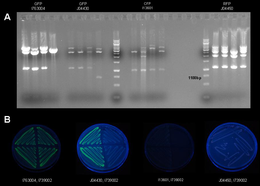
Figure 10: 1% agarose gel of XbaI/PstI test restriction digests of plasmid [http://partsregistry.org/Part:pSB3K3 pSB3K3] holding fluorescent protein generators [http://partsregistry.org/Part:BBa_I763004 I763004], [http://partsregistry.org/Part:BBa_J04430 J04430], [http://partsregistry.org/Part:BBa_I13601 I13601] and [http://partsregistry.org/Part:BBa_J5526 J5526]. After ligation four colonies were picked per construct and a test restriction digest was carried out to identify the plasmids holding the correct inserts.
Once the assembly has been completed, the constructs will be tested for leaky expression, expression upon IPTG induction and expression upon tetracycline induction during presence of IPTG.
References
(1) Rosenberg, A. H., Lade, B. N., Chui, D. S., Lin, S. W., Dunn, J. J., and Studier, F. W. (1987) Vectors for selective expression of cloned DNAs by T7 RNA polymerase. Gene 56, 125-35.
(2) Studier, F. W., and Moffatt, B. A. (1986) Use of bacteriophage T7 RNA polymerase to direct selective high-level expression of cloned genes. J Mol Biol 189, 113-30.
(3) Studier, F. W., Rosenberg, A. H., Dunn, J. J., and Dubendorff, J. W. (1990) Use of T7 RNA polymerase to direct expression of cloned genes. Methods Enzymol 185, 60-89.
(4) Beumer, K., Bhattacharyya, G., Bibikova, M., Trautman, J. K., and Carroll, D. (2006) Efficient gene targeting in Drosophila with zinc-finger nucleases. Genetics 172, 2391-403.
(5) Bibikova, M., Beumer, K., Trautman, J. K., and Carroll, D. (2003) Enhancing gene targeting with designed zinc finger nucleases. Science 300, 764.
(6) Carroll, D. (2008) Progress and prospects: Zinc-finger nucleases as gene therapy agents. Gene Ther.
(7) Carroll, D., Morton, J. J., Beumer, K. J., and Segal, D. J. (2006) Design, construction and in vitro testing of zinc finger nucleases. Nat Protoc 1, 1329-41.
(8) Suckow, J., Markiewicz, P., Kleina, L. G., Miller, J., Kisters-Woike, B., and Muller-Hill, B. (1996) Genetic studies of the Lac repressor. XV: 4000 single amino acid substitutions and analysis of the resulting phenotypes on the basis of the protein structure. J Mol Biol 261, 509-23.
(9) Saenger, W., Orth, P., Kisker, C., Hillen, W., and Hinrichs, W. (2000) The Tetracycline Repressor-A Paradigm for a Biological Switch. Angew Chem Int Ed Engl 39, 2042-2052.
(10) Hinrichs, W., Kisker, C., Duvel, M., Muller, A., Tovar, K., Hillen, W., and Saenger, W. (1994) Structure of the Tet repressor-tetracycline complex and regulation of antibiotic resistance. Science 264, 418-20.
(11) Gilbert, W., and Muller-Hill, B. (1966) Isolation of the Lac Repressor. Proc Natl Acad Sci U S A 56, 1891-1898.
(12) Calos, M. P., Galas, D., and Miller, J. H. (1978) Genetic studies of the lac repressor. VIII. DNA sequence change resulting from an intragenic duplication. J Mol Biol 126, 865-9.
(13) Coulondre, C., and Miller, J. H. (1977) Genetic studies of the lac repressor. III. Additional correlation of mutational sites with specific amino acid residues. J Mol Biol 117, 525-67.
(14) Coulondre, C., and Miller, J. H. (1977) Genetic studies of the lac repressor. IV. Mutagenic specificity in the lacI gene of Escherichia coli. J Mol Biol 117, 577-606.
(15) Farabaugh, P. J., Schmeissner, U., Hofer, M., and Miller, J. H. (1978) Genetic studies of the lac repressor. VII. On the molecular nature of spontaneous hotspots in the lacI gene of Escherichia coli. J Mol Biol 126, 847-57.
(16) Kleina, L. G., and Miller, J. H. (1990) Genetic studies of the lac repressor. XIII. Extensive amino acid replacements generated by the use of natural and synthetic nonsense suppressors. J Mol Biol 212, 295-318.
(17) Markiewicz, P., Kleina, L. G., Cruz, C., Ehret, S., and Miller, J. H. (1994) Genetic studies of the lac repressor. XIV. Analysis of 4000 altered Escherichia coli lac repressors reveals essential and non-essential residues, as well as "spacers" which do not require a specific sequence. J Mol Biol 240, 421-33.
(18) Miller, J. H. (1979) Genetic studies of the lac repressor. XI. On aspects of lac repressor structure suggested by genetic experiments. J Mol Biol 131, 249-58.
(19) Miller, J. H. (1984) Genetic studies of the lac repressor. XII. Amino acid replacements in the DNA binding domain of the Escherichia coli lac repressor. J Mol Biol 180, 205-12.
(20) Miller, J. H., Coulondre, C., Hofer, M., Schmeissner, U., Sommer, H., Schmitz, A., and Lu, P. (1979) Genetic studies of the lac repressor. IX. Generation of altered proteins by the suppression of nonsence mutations. J Mol Biol 131, 191-222.
(21) Miller, J. H., Ganem, D., Lu, P., and Schmitz, A. (1977) Genetic studies of the lac repressor. I. Correlation of mutational sites with specific amino acid residues: construction of a colinear gene-protein map. J Mol Biol 109, 275-98.
(22) Miller, J. H., and Schmeissner, U. (1979) Genetic studies of the lac repressor. X. Analysis of missense mutations in the lacI gene. J Mol Biol 131, 223-48.
(23) Schmeissner, U., Ganem, D., and Miller, J. H. (1977) Genetic studies of the lac repressor. II. Fine structure deletion map of the lacI gene, and its correlation with the physical map. J Mol Biol 109, 303-26.
(24) Schmitz, A., Coulondre, C., and Miller, J. H. (1978) Genetic studies of the lac repressor. V. Repressors which bind operator more tightly generated by suppression and reversion of nonsense mutations. J Mol Biol 123, 431-54.
(25) Sommer, H., Schmitz, A., Schmeissner, U., and Miller, J. H. (1978) Genetic studies of the lac repressor. VI. The B116 repressor: an altered lac repressor containing amino acid specified by both the trp and lacI leader regions. J Mol Biol 123, 457-69.
(26) Friedman, A. M., Fischmann, T. O., and Steitz, T. A. (1995) Crystal structure of lac repressor core tetramer and its implications for DNA looping. Science 268, 1721-7.
(27) Lewis, M., Chang, G., Horton, N. C., Kercher, M. A., Pace, H. C., Schumacher, M. A., Brennan, R. G., and Lu, P. (1996) Crystal structure of the lactose operon repressor and its complexes with DNA and inducer. Science 271, 1247-54.
(28) Yamagishi, M., Matsushima, H., Wada, A., Sakagami, M., Fujita, N., and Ishihama, A. (1993) Regulation of the Escherichia coli rmf gene encoding the ribosome modulation factor: growth phase- and growth rate-dependent control. Embo J 12, 625-30.
(29) Wada, A., Yamazaki, Y., Fujita, N., and Ishihama, A. (1990) Structure and probable genetic location of a "ribosome modulation factor" associated with 100S ribosomes in stationary-phase Escherichia coli cells. Proc Natl Acad Sci U S A 87, 2657-61.
(30) Yoshida, H., Yamamoto, H., Uchiumi, T., and Wada, A. (2004) RMF inactivates ribosomes by covering the peptidyl transferase centre and entrance of peptide exit tunnel. Genes Cells 9, 271-8.
(31) Yoshida, H., Maki, Y., Kato, H., Fujisawa, H., Izutsu, K., Wada, C., and Wada, A. (2002) The ribosome modulation factor (RMF) binding site on the 100S ribosome of Escherichia coli. J Biochem 132, 983-9.
 "
"


