Team:NYMU-Taipei/Project/Time Regulation
From 2008.igem.org
Blackrabbit (Talk | contribs) |
Blackrabbit (Talk | contribs) |
||
| (One intermediate revision not shown) | |||
| Line 46: | Line 46: | ||
{| border="1" | {| border="1" | ||
|- | |- | ||
| - | | [[Image:NYMU_timer_circuit.png| | + | | [[Image:NYMU_timer_circuit0.png|310px]] |
| - | | [[Image:NYMU_timer_circuit_bb.png| | + | | [[Image:NYMU_timer_circuit.png|310px]] |
| + | | [[Image:NYMU_timer_circuit_bb.png|310px]] | ||
|} | |} | ||
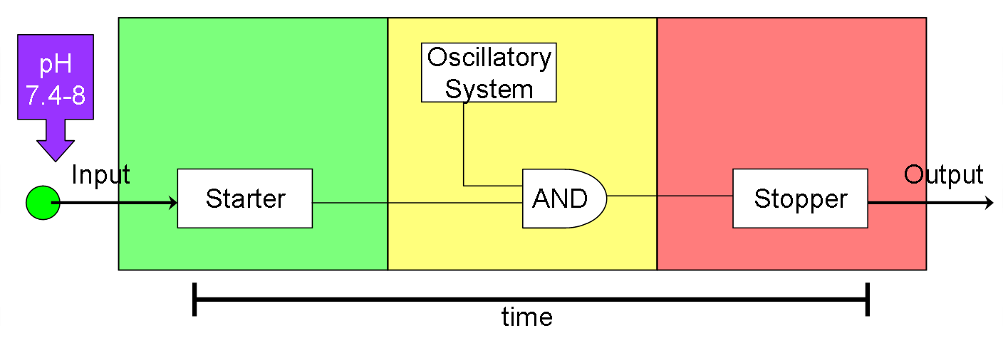
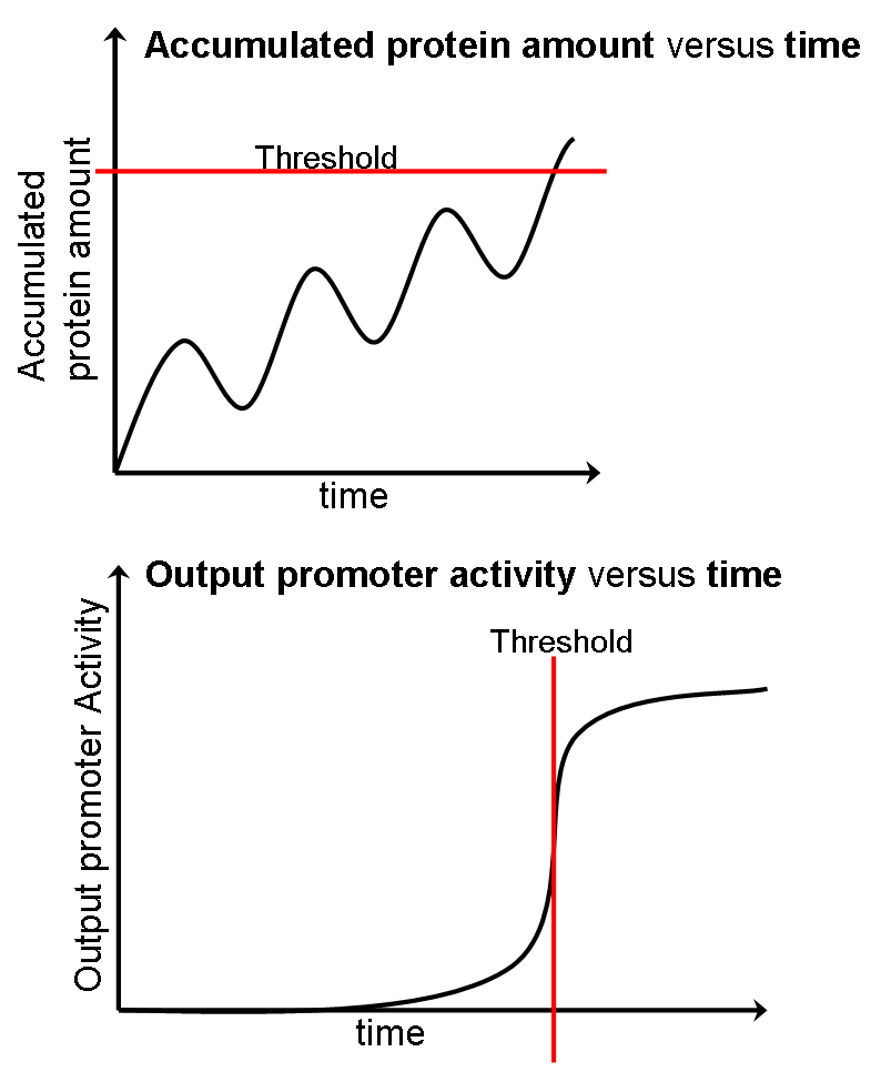
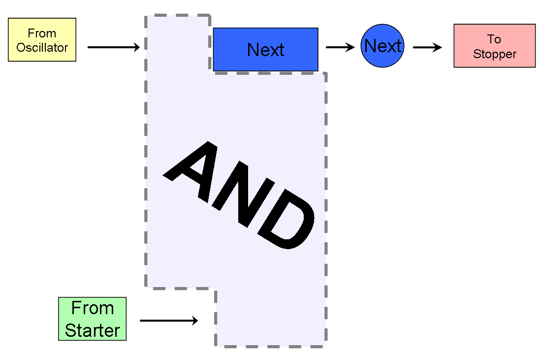
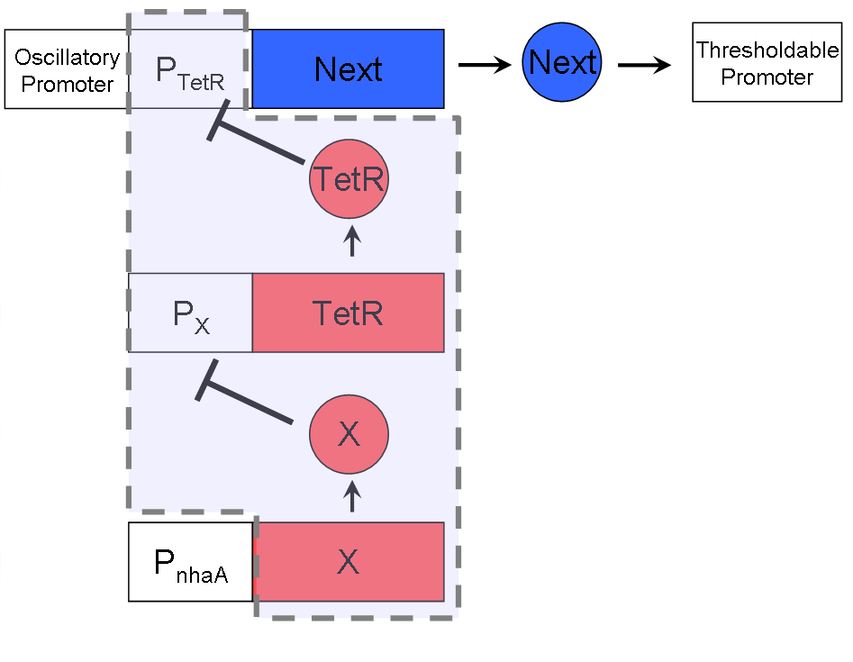
| - | * The | + | * The three figures above show the circuit design for the timer. The first is looking at it from a higher view, the second is in a more logical circuit design view, and the third is the more physical design with biobricks pictures. |
| + | * The Legend for the second picture: | ||
** The Oscillatory Promoter comes from the whichever oscillator is being used. | ** The Oscillatory Promoter comes from the whichever oscillator is being used. | ||
** pX is a repressable promoter (and X is the gene that can repress it). | ** pX is a repressable promoter (and X is the gene that can repress it). | ||
** The light blue shaded area represent's the circuit's logic AND gate. | ** The light blue shaded area represent's the circuit's logic AND gate. | ||
** The dark blue gene "Next" expresses a protein that accumulates to be used for the thresholdable promoter. | ** The dark blue gene "Next" expresses a protein that accumulates to be used for the thresholdable promoter. | ||
| - | |||
== Experimental Results == | == Experimental Results == | ||
Latest revision as of 23:29, 29 October 2008
| Home | Project Overview: | pH Sensor | Attachment | Time Regulation | Waste Removal | Experiments and Parts | About Us |
We, the subteam self-proclaimed as the regulators of time, control time through the use of a timer and oscillators. Our goal is to design a subsystem such that it would set to detach after a specified amount of time.
Contents |
Motivation
To enhance the the effect of the micro dialysis machine in the intestine lumen, the half life of the micro dialysis machine is designed to be prolonged. However, since our micro dialysis machine is made in the chassis of E. coli, there are two possible risks while staying in the intestine too long. One is that the E. coli may be apoptosis or necrosis due to large amount of the metabolite wastes it absorbed. The other is the bacteria balance in the intestine may be disturbed thanks to the E. coli being added. Thus, it's crucial and necessary to have a timer in our micro dialysis machine. Besides, the timer has many biological and engineering application, such as artificial pacemakers, biological clocks, etc.
Timer Design
Our timer consists of three parts: starting the timer, counting the time, and "stopping" the timer.
Timer Start
We want our timer to start when our BacToKidney attaches to the small intestine. It attaches to the small intestine using the pH Sensor's pNhaA, so we also use the same promoter to start our timer.
Counting Time
Counting time using oscillators is the part we spent most of our time doing. For our timer, we have created an "oscillatory interface" which allows one to substitute any oscillator to be used with our timer.
Oscillatory Interface
Our interface only requires that there exist a promoter in the oscillatory system such that it shows an oscillatory effect due to the oscillator being in the same cell. We call this the Oscillatory Promoter.
For example, in the Reloxilator, the pRE promoter has an oscillatory effect, and is therefore the oscillatory promoter for the Reloxilator.
Our Oscillators
Since any oscillator could be used as long as it confirms to our oscillatory interface, we decided to make two oscillators with very different time periods to fit our purposes:
Cyanoxilator (Cyanobacterial Oscillator)
| Reloxilator (Relaxation Oscillator)
|
Timer Stop
Timer Circuit Design
| 
| 
|
- The three figures above show the circuit design for the timer. The first is looking at it from a higher view, the second is in a more logical circuit design view, and the third is the more physical design with biobricks pictures.
- The Legend for the second picture:
- The Oscillatory Promoter comes from the whichever oscillator is being used.
- pX is a repressable promoter (and X is the gene that can repress it).
- The light blue shaded area represent's the circuit's logic AND gate.
- The dark blue gene "Next" expresses a protein that accumulates to be used for the thresholdable promoter.
Experimental Results
So far, we've finished constructing all of the Cyanoxilator and have done a few reporting assays. For the Reloxilator, all the separate components (the oscillator, tuner, synchronizer, and reporter) have been constructed, but only the oscillator, tuner and reporter have been successfully ligated together. A few reporting assays were also performed on the oscillator-tuner-reporter construct.
 "
"

