Team:UNIPV-Pavia/Project
From 2008.igem.org
| (46 intermediate revisions not shown) | |||
| Line 1: | Line 1: | ||
| - | |||
| - | |||
{| style="color:#000000;background-color:#ffffff;" cellpadding="3" cellspacing="1" border="3" bordercolor="#3128" width="80%" align="center" | {| style="color:#000000;background-color:#ffffff;" cellpadding="3" cellspacing="1" border="3" bordercolor="#3128" width="80%" align="center" | ||
!align="center"|[[Image:home.jpg|30px]] [[Team:UNIPV-Pavia|Home]] | !align="center"|[[Image:home.jpg|30px]] [[Team:UNIPV-Pavia|Home]] | ||
| Line 294: | Line 292: | ||
==Applications== | ==Applications== | ||
| + | Mux and Demux are two fundamental devices in electronics. They are used in several applications, for example in communication devices, in Arithmetic Logic Units (ALUs), or, in general, in applications that involve channel sharing. | ||
| + | <br> | ||
| + | Analogously, they could play a crucial role in the building of complex genetic circuits. In fact, both of them can be used as controlled genetic switches. | ||
| + | <br> | ||
| + | Because our devices had been designed to be general, their application field is very wide. For example, genetic Mux can be used to integrate signals from the environment in a two-inputs and one-output biosensor; once detected, the selector controls which of the two inputs must be transferred in output. In this way, two sensing devices can be integrated in only one circuit that can compute multiplexing logic function. | ||
| + | On the other hand, genetic Demux can be used for controlled protein productions, where the choice of the protein to produce is made by the selector. In this case, we can imagine an industrial process where two consequent enzyme reactions are necessary to build a final product. Using a Demux, we can consider the two enzymes as system outputs and then we can easily switch on and off their production modulating selection signal. | ||
| + | <br> | ||
| + | Selector in Mux and Demux can be set manually, but also controlled automatically. In fact, it is possible to use feedback control to pilot the selector. For example, in Demux it is possible to switch the enzyme production when a specific condition (for example a pH threshold) is reached. | ||
| + | <br> | ||
| + | Switching activity in these two devices is a very powerful tool to manage multi-input and multi-output systems. | ||
== Experiments and results == | == Experiments and results == | ||
| Line 311: | Line 319: | ||
|[[Image:pv_assemblyschema.png|thumb|600px|left|Assembly tree schema]] | |[[Image:pv_assemblyschema.png|thumb|600px|left|Assembly tree schema]] | ||
|} | |} | ||
| + | See [https://2008.igem.org/Team:UNIPV-Pavia/Parts PARTS] section for sequencing results of our assemblies. | ||
=== Functional tests === | === Functional tests === | ||
We performed these boolean (on/off) fluorescence tests: | We performed these boolean (on/off) fluorescence tests: | ||
<br> | <br> | ||
| - | + | <hr> | |
| - | + | *'''TEST 1''' | |
| - | + | <br> | |
| - | + | {|align="center" | |
| - | + | |[[Image:pv_test1.png|thumb|250px|left|GFP protein generator under Plambda]] | |
| + | |} | ||
| + | '''Description:''' we assembled an available GFP protein generator (E0240) under Plambda promoter, keeping pSB1A2 as the scaffold vector. | ||
| + | <br> | ||
| + | '''Motivation:''' cI protein was not present, so Plambda should work like a constitutive promoter. A reporter gene downstream of this promoter allows us to validate Plambda costitutive activity. That can be very useful to validate our NOT logic gate. | ||
| + | <br> | ||
| + | '''Methods:''' after ligation reaction of R0051 and E0240, we transformed ligation product using Invitrogen TOP10 cells and plated transformed bacteria. Then we watched the plate on the transluminator to check if positive transformants glowed under UV rays. We also picked up a fluorescent colony with a tip and infected 1 ml of LB + Amp. After 3 hours at 37°C, 220 rpm we watched 50 ul of the culture at microscope through FITC channel and DAPI channel for negative control. | ||
| + | <br> | ||
| + | '''Results:''' positive transformants glowed under UV rays and green fluorescent cells could be observed at microscope (see figure). | ||
| + | {|align="center" | ||
| + | |[[Image:pv_fig_test1.png|thumb|400px|left|TOP10 cells at microscope]] | ||
| + | |} | ||
| + | <br> | ||
| + | '''Comments:''' this experiment confirmed that GFP was expressed in positive transformants, so Plambda activity was qualitatively validated. | ||
| + | <br> | ||
| + | <hr> | ||
| + | <hr> | ||
| + | *'''TEST 2''' | ||
| + | <br> | ||
| + | {|align="center" | ||
| + | |[[Image:pv_test2.png|thumb|250px|left|GFP protein generator under Ptet]] | ||
| + | |} | ||
| + | '''Description:''' we assembled E0240 under Ptet promoter, keeping pSB1A2 as the scaffold vector. | ||
| + | <br> | ||
| + | '''Motivation:''' tetR protein was not present, so Ptet should work like a constitutive promoter. A reporter gene downstream of this promoter allows us to validate Ptet costitutive activity. Ptet is useful for specific input building. | ||
| + | <br> | ||
| + | '''Methods:''' after ligation reaction of R0040 and E0240, we transformed ligation product using Invitrogen TOP10 cells and plated transformed bacteria. Then we watched the plate on the transluminator to check if positive transformants glowed under UV rays. We also picked up a fluorescent colony with a tip and infected 1 ml of LB + Amp. After 3 hours at 37°C, 220 rpm we watched 50 ul of the culture at microscope through FITC channel and DAPI channel for negative control. | ||
| + | <br> | ||
| + | '''Results:''' positive transformants glowed under UV rays and green fluorescent cells could be observed at microscope (see figure). | ||
| + | {|align="center" | ||
| + | |[[Image:pv_fig_test2.png|thumb|400px|left|TOP10 cells at microscope]] | ||
| + | |} | ||
| + | <br> | ||
| + | '''Comments:''' this experiment confirmed that GFP was expressed in positive transformants, so Ptet activity was qualitatively validated. | ||
| + | <br> | ||
| + | <hr> | ||
| + | <hr> | ||
| + | *'''TEST 3''' | ||
| + | <br> | ||
| + | {|align="center" | ||
| + | |[[Image:pv_test3.png|thumb|250px|left|RFP protein generator under constitutive promoter]] | ||
| + | |} | ||
| + | '''Description:''' we didn't perform any assembly for this experiment, because the promoter we wanted to test was contained into BBa_J61002 vector, which places a RFP protein generator between SpeI and PstI restriction sites. | ||
| + | <br> | ||
| + | '''Motivation:''' J23100, which we call Pcon, should have a strong constitutive activity. A reporter gene downstream of this promoter allows us to validate this activity. Pcon is useful to build our inputs because some sensors like IPTG and Tetracycline sensors need the constitutive production of specific proteins, in this case lacI and tetR respectively. | ||
| + | <br> | ||
| + | '''Methods''' we transformed J23100 using Invitrogen TOP10 and plated transformed bacteria. We expected to observe red fluorescence (using transluminator) in all the colonies. We also picked up a colony with a tip and infected 1 ml of LB + Amp. After 3 hours at 37°C, 220 rpm we watched 50 ul of the culture at microscope through TRITC channel and DAPI channel for negative control. | ||
| + | <br> | ||
| + | '''Results:''' all the grown colonies glowed under UV rays and red fluorescent cells could be observed at microscope (see figure). | ||
| + | {|align="center" | ||
| + | |[[Image:pv_fig_test3.png|thumb|400px|left|TOP10 cells at microscope]] | ||
| + | |} | ||
| + | <br> | ||
| + | '''Comments:''' this experiment confirmed that RFP was expressed in transformed bacteria, so Pcon functionality was qualitatively validated. | ||
| + | <br> | ||
| + | <hr> | ||
| + | <hr> | ||
| + | *'''TEST 4''' | ||
| + | <br> | ||
| + | {|align="center" | ||
| + | |[[Image:pv_test4.png|thumb|250px|left|Our GFP protein generator (K081012) under a constitutive promoter]] | ||
| + | |} | ||
| + | '''Description:''' we assembled a constitutive promoter family member (J23100) upstream of K081012, a GFP protein generator we built. We decided to excide J23100 from its plasmid (E-S) and to open K081012 plasmid (pSB1AK3) (E-X). | ||
| + | <br> | ||
| + | '''Motivation:''' we already validated qualitatively J23100 constitutive activity, so this promoter can be used to test the GFP protein generator we built. We wanted to check if K081012 actually generates GFP. | ||
| + | <br> | ||
| + | '''Methods''' after ligation reaction of J23100 and K081012, we transformed ligation product using Invitrogen TOP10 cells and plated transformed bacteria. Then we watched the plate on the transluminator to check if positive transformants glowed under UV rays. We also picked up a fluorescent colony with a tip and infected 1 ml of LB + Amp. After 3 hours at 37°C, 220 rpm we watched 50 ul of the culture at microscope through FITC channel and DAPI channel for negative control. | ||
| + | <br> | ||
| + | '''Results:''' positive transformants glowed under UV rays (see figure) and green fluorescent cells could be observed at microscope (see figure). | ||
| + | {|align="center" | ||
| + | |[[Image:pv_fig_test4bis.jpg|thumb|400px|left|TOP10 colonies under UV]] | ||
| + | |} | ||
| + | {|align="center" | ||
| + | |[[Image:pv_fig_test4.png|thumb|400px|left|TOP10 cells at microscope]] | ||
| + | |} | ||
| + | <br> | ||
| + | '''Comments:''' this experiment confirmed that our GFP protein generator actually generates GFP. | ||
| + | <br> | ||
| + | <hr> | ||
| + | <hr> | ||
| + | *'''TEST 5''' | ||
| + | <br> | ||
| + | {|align="center" | ||
| + | |[[Image:pv_test5.png|thumb|250px|left|Our RFP protein generator (K081014) under a constitutive promoter]] | ||
| + | |} | ||
| + | '''Description:''' we assembled a constitutive promoter family member (J23100) upstream of K081014, a RFP protein generator we built. We decided to excide J23100 from its plasmid (E-S) and to open K081014 plasmid (pSB1AK3) (E-X). | ||
| + | <br> | ||
| + | '''Motivation:''' we already validated qualitatively J23100 constitutive activity, so this promoter can be used to test the RFP protein generator we built. We wanted to check if K081014 actually generates RFP. | ||
| + | <br> | ||
| + | '''Methods''' after ligation reaction of J23100 and K081014, we transformed ligation product using Invitrogen TOP10 cells and plated transformed bacteria. Then we watched the plate on the transluminator to check if positive transformants glowed under UV rays. We also picked up a fluorescent colony with a tip and infected 1 ml of LB + Amp. After 3 hours at 37°C, 220 rpm we watched 50 ul of the culture at microscope through TRITC channel and DAPI channel for negative control. | ||
| + | <br> | ||
| + | '''Results:''' positive transformants glowed under UV rays (see figure) and red fluorescent cells could be observed at microscope (see figure). | ||
| + | {|align="center" | ||
| + | |[[Image:pv_fig_test5bis.jpg|thumb|400px|left|TOP10 colonies under UV]] | ||
| + | |} | ||
| + | {|align="center" | ||
| + | |[[Image:pv_fig_test5.png|thumb|400px|left|TOP10 cells at microscope]] | ||
| + | |} | ||
| + | <br> | ||
| + | '''Comments:''' this experiment confirmed that our RFP protein generator actually generates RFP. | ||
| + | <br> | ||
| + | <hr> | ||
| + | <hr> | ||
| + | *'''TEST 6''' | ||
| + | <br> | ||
| + | {|align="center" | ||
| + | |[[Image:pv_test6.png|thumb|350px|left|GFP protein generator under Plux]] | ||
| + | |} | ||
| + | '''Description:''' we assembled K081012 (our GFP) under the Plux promoter that was contained into K081000. We kept pSB1A2 as the scaffold vector. | ||
| + | <br> | ||
| + | '''Motivation:''' we didn't assemble any input to K081000 device, so we could study only the promoter basic activity. We expected to find a weak basic activity. Plux is useful for our AND logic gate. | ||
| + | <br> | ||
| + | '''Methods:''' after ligation reaction of K081000 and K081012, we transformed ligation product using Invitrogen TOP10 cells and plated transformed bacteria. Then we performed a screening on 5 colonies through colony PCR to search for correctly ligated plasmid. We infected 9 ml of LB + Amp with the chosen colony and incubated the culture at 37°C, 220 rpm for 15 hours. Then we watched 50 ul of the culture at microscope through FITC channel and DAPI channel for negative control. | ||
| + | <br> | ||
| + | '''Results:''' green fluorescent cells could not be observed at microscope (see figure). | ||
| + | {|align="center" | ||
| + | |[[Image:pv_fig_test6.png|thumb|400px|left|No fluorescent TOP10 cells can be seen at microscope]] | ||
| + | |} | ||
| + | <br> | ||
| + | '''Comments:''' the picture above was taken using the same gain and exposition time as the previous experiments and with these parameters we cannot see any green fluorescent bacteria. Increasing exposition time, green fluorescence could be observed (picture not reported). So, we can say that GFP was expressed very weakly. This experiment confirmed that Plux promoter has a weak activity without luxI and luxR proteins. | ||
| + | <br> | ||
| + | <hr> | ||
| + | <hr> | ||
| + | *'''TEST 7''' | ||
| + | <br> | ||
| + | {|align="center" | ||
| + | |[[Image:pv_test7.png|thumb|350px|left|GFP protein generator under Plas]] | ||
| + | |} | ||
| + | '''Description:''' we assembled K081012 (our GFP) under the Plas promoter that was contained into K081001. We kept pSB1A2 as the scaffold vector. | ||
| + | <br> | ||
| + | '''Motivation:''' we didn't assemble any input to K081001 device, so we could study only the promoter basic activity. We expected to find a weak basic activity. Plas is useful for our AND logic gate. | ||
| + | <br> | ||
| + | '''Methods:''' after ligation reaction of K081001 and K081012, we transformed ligation product using Invitrogen TOP10 cells and plated transformed bacteria. Then we performed a screening on 5 colonies through colony PCR to search for correctly ligated plasmid. We infected 9 ml of LB + Amp with the chosen colony and incubated the culture at 37°C, 220 rpm for 15 hours. Then we watched 50 ul of the culture at microscope through FITC channel and DAPI channel for negative control. | ||
| + | <br> | ||
| + | '''Results:''' green fluorescent cells could not be observed at microscope (see figure). | ||
| + | {|align="center" | ||
| + | |[[Image:pv_fig_test7.png|thumb|400px|left|No fluorescent TOP10 cells can be seen at microscope]] | ||
| + | |} | ||
| + | <br> | ||
| + | '''Comments:''' the picture above was taken using the same gain and exposition time as the previous experiments and with these parameters we cannot see any green fluorescent bacteria. Increasing exposition time, green fluorescence could be observed (picture not reported). So, we can say that GFP was expressed very weakly. This experiment confirmed that Plas promoter has a weak activity without lasI and lasR proteins. | ||
| + | <br> | ||
| + | <hr> | ||
| + | <hr> | ||
| + | *'''TEST 8''' | ||
| + | <br> | ||
| + | {|align="center" | ||
| + | |[[Image:pv_test8.png|thumb|600px|left|GFP protein generator under Plux and constitutive expression of luxI and luxR]] | ||
| + | |} | ||
| + | '''Description:''' we assembled K081012 (our GFP) under the Plux promoter that was contained into K081000. We also assembled K081011 upstream of K081000. We kept pSB1A2 as the scaffold vector. | ||
| + | <br> | ||
| + | '''Motivation:''' Plux promoter activity was studied in response of a constitutive expression of luxI and luxR. Plambda promoter without cI repressor guaranteed the constitutive expression of these genes. We expected to find a strong activity because Plux is turned on. lux system is useful for our AND logic gate. | ||
| + | <br> | ||
| + | '''Methods:''' we ligated K081012 under K081000, transformed ligation, plated transformed bacteria, performed PCR screening on some colonies and extracted correctly ligated plasmids. We repeated these steps to assemble K081011 upstream of K081000-K081012, but we didn't perform PCR screening. Then we watched the plate on the transluminator to check if positive transformants glowed under UV rays. We also picked up a fluorescent colony with a tip and infected 1 ml of LB + Amp. After 3 hours at 37°C, 220 rpm we watched 50 ul of the culture at microscope through FITC channel and DAPI channel for negative control. | ||
| + | <br> | ||
| + | '''Results:''' positive transformants glowed under UV rays and green fluorescent cells could be observed at microscope (see figure). | ||
| + | {|align="center" | ||
| + | |[[Image:pv_fig_test8.png|thumb|400px|left|TOP10 cells at microscope]] | ||
| + | |} | ||
| + | <br> | ||
| + | '''Comments:''' this experiment confirmed that Plux promoter can be activated by the contemporary presence of luxI and luxR. This is a crucial result for our AND logic gate. | ||
| + | <br> | ||
| + | <hr> | ||
| + | <hr> | ||
| + | *'''TEST 9''' | ||
| + | <br> | ||
| + | {|align="center" | ||
| + | |[[Image:pv_test9.png|thumb|500px|left|GFP protein generator under Plux and constitutive expression of luxR]] | ||
| + | |} | ||
| + | '''Description:''' we assembled K081012 (our GFP) under the Plux promoter that was contained into K081022. We kept pSB1A2 as the scaffold vector. | ||
| + | <br> | ||
| + | '''Motivation:''' Plux promoter activity was studied in response to a constitutive expression of luxR. Plambda promoter without cI repressor guaranteed the constitutive expression of this gene. We expected to find a weak activity because luxR transcription factor is not active and so Plux cannot be turned on. We also expected to find a strong activity if we induce luxR activation using 3OC6-HSL (this is equivalent to TEST 8 conditions, because 3OC6-HSL is synthesized by luxI). lux system is useful for our AND logic gate. | ||
| + | <br> | ||
| + | '''Methods:''' we ligated K081012 downstream of K081022, transformed ligation, plated transformed bacteria and screened three colonies to insulate a colony containing correctly ligated plasmids. We inoculated the positive colony into 9 ml of LB + Amp and incubated the culture at 37°C, 220 rpm for 15 hours. Then we diluted 1:10 the culture in two falcon tubes (5 ml cultures). One of these cultures was induced with 3OC6-HSL 1 uM. We let the two cultures grow for 2 hours and then we watched 50 ul at microscope through FITC channel and DAPI channel for negative control. | ||
| + | <br> | ||
| + | '''Results:''' green fluorescent cells could not be observed at microscope (see figure) for the non induced culture, while they could be observed for the induced culture. | ||
| + | {|align="center" | ||
| + | |[[Image:pv_fig_test9.png|thumb|400px|left|Non induced culture: TOP10 cells cannot be seen at microscope]] | ||
| + | |} | ||
| + | {|align="center" | ||
| + | |[[Image:pv_fig_test9bis.png|thumb|400px|left|Induced culture: fluorescent TOP10 cells at microscope]] | ||
| + | |} | ||
| + | {|align="center" | ||
| + | |[[Image:pv_fig_test9superexp.png|thumb|400px|left|Same frames as above, but superexposed: non induced (left) and induced (right) cultures]] | ||
| + | |} | ||
| + | <br> | ||
| + | '''Comments:''' the pictures above was taken using the same gain and exposition time as the previous experiments and with these parameters we cannot see any green fluorescent bacteria for the non induced culture, while we can see green fluorescent TOP10 in the induced culture. As we wrote for TEST 6 and TEST 7, increasing exposition time green fluorescence could be observed even for the non induced culture (last picture), confirming the weak activity of Plux promoter in response of unactive luxR. This experiment confirmed that Plux promoter has a weak activity without luxI (or 3OC6-HSL) and luxR protein is not sufficient to induce a strong transcription. Adding 3OC6-HSL, luxR becomes active and so Plux is turned on. | ||
| + | <br> | ||
| + | NOTE: K081022 has a point mutation in position 349 of C0062 coding sequence. This mutation changes the aminoacid, but luxR seems to work as expected. | ||
| + | <br> | ||
| + | <hr> | ||
| + | <hr> | ||
| + | *'''TEST 10''' | ||
| + | <br> | ||
| + | {|align="center" | ||
| + | |[[Image:pv_test10.png|thumb|600px|left|RFP protein generator under Plux and constitutive expression of luxR]] | ||
| + | |} | ||
| + | '''Description:''' this test is equivalent to TEST 9: we assembled K081014 (our RFP) under the Plux promoter that was contained into K081004. We kept pSB1AK3 as the scaffold vector. | ||
| + | <br> | ||
| + | '''Motivation:''' we wanted to repeat TEST 9 experiment using a longer construct and a different reporter gene. | ||
| + | <br> | ||
| + | '''Methods:''' the same as TEST 9, but using K081004 instead of K081022 and using RFP (K081014) instead of GFP (K081012). | ||
| + | <br> | ||
| + | '''Results:''' red fluorescent cells could not be observed at microscope (see figure) for the non induced culture, while they could be observed for the induced culture. | ||
| + | {|align="center" | ||
| + | |[[Image:pv_fig_test10.png|thumb|400px|left|Non induced culture: TOP10 cells cannot be seen at microscope]] | ||
| + | |} | ||
| + | {|align="center" | ||
| + | |[[Image:pv_fig_test10bis.png|thumb|400px|left|Induced culture: fluorescent TOP10 cells at microscope]] | ||
| + | |} | ||
| + | {|align="center" | ||
| + | |[[Image:pv_fig_test10superexp.png|thumb|400px|left|Same frames as above, but superexposed: non induced (left) and induced (right) cultures]] | ||
| + | |} | ||
| + | <br> | ||
| + | '''Comments:''' the same as TEST 9. | ||
| + | <br> | ||
| + | NOTE: C0062 has the same mutation described in TEST 9. We also performed this test with an old version of K081004 carrying another point mutation (C->T at position 704 of C0062 coding sequence) that changed an aminoacid. Even in this case K081004 seemed to work as expected (results not shown). | ||
| + | <br> | ||
| + | <hr> | ||
| + | <hr> | ||
| + | *'''TEST 11''' | ||
| + | <br> | ||
| + | {|align="center" | ||
| + | |[[Image:pv_test11.png|thumb|600px|left|Terminator efficiency test]] | ||
| + | |} | ||
| + | '''Description:''' we assembled K081014 (our RFP) under the artificial 39 bp terminator (B1006) that is at the end of K081022-K081012 (composite part used for TEST 9). We kept pSB1A2 as the scaffold vector. | ||
| + | <br> | ||
| + | '''Motivation:''' we wanted to test qualitatively if our terminator actually stops transcription. | ||
| + | <br> | ||
| + | '''Methods:''' we assembled K081014 downstream of K081022, transformed ligation, plated transformed bacteria and insulated a colony containing correctly ligated plasmid. We inoculated the colony into 9 ml of LB + Amp and incubated the culture at 37°C, 220 rpm for 15 hours. Then we diluted 1:10 the culture in two falcon tubes (5 ml cultures). One of these cultures was induced with 3OC6-HSL 1 uM. We let the two cultures grow for 2 hours and then we watched 50 ul at microscope through FITC channel (positive control), TRITC channel and DAPI channel (negative control). | ||
| + | <br> | ||
| + | '''Results:''' soon | ||
| + | <br> | ||
| + | '''Comments:''' soon | ||
| + | <br> | ||
| + | <br> | ||
| + | <hr> | ||
| + | <br> | ||
| + | We also performed these quantitative fluorescence tests: | ||
| + | <hr> | ||
| + | *'''TEST A''' | ||
| + | <br> | ||
| + | '''Description:''' this test is an extension of TEST 9. We induced six cultures with 3OC6-HSL at different concentrations to study quantitatively HSL-GFP static transfer function. | ||
| + | <br> | ||
| + | '''Motivation:''' we want to know cutoff point of this device. | ||
| + | <br> | ||
| + | '''Methods:''' the same as TEST 9, but we diluted the overnight 9 ml culture 1:10 in six falcon tubes (5 ml cultures). We induced the six cultures with 3OC6-HSL 0 nM, 0.1 nM, 1 nM, 10 nM, 100 nM and 1 uM respectively. We incubated the cultures at 37°C, 220 rpm for 2 hours and then we watched 50 ul at microscope through FITC channel and DAPI channel for negative control. We prepared two 50 ul glasses for each culture. We acquired three frames at 2.5 s (maximum exposition time) and 10 ms exposition time for every sample. We used ImageJ software to count automatically the number of cells for every frame. Then we computed n10/n2.5 (where n is the number of cells) to calculate the percentage of cells that glowed in the 10 ms acquisition, assuming that in the 2.5 s acquisition we can see the total number of cells. For each HSL concentration, we calculated the mean value of the 6 statistics (3 frames for each of the 2 glasses). | ||
| + | <br> | ||
| + | '''Results:''' | ||
| + | {|align="center" | ||
| + | |[[Image:pv_fig_test1q.png|thumb|600px|left|GFP (arbitrary units) vs 3OC6-HSL concentration: 1=0nM, 2=0.1nM, 3=1nM, 4=10nM, 5=100nM, 6=1uM]] | ||
| + | |} | ||
| + | <br> | ||
| + | '''Comments:''' we computed the statistic n10/n2.5 because we know that when fluorescence is weak, cells cannot be seen at low exposition times. So, we calculate the ratio between the cells we can see at a low exposition time and the total number of cells in the frame. We chose 10 ms because the previous experiments with GFP had been performed using this parameter. We know that this is not an exact statistic, in fact we have to consider the count errors of ImageJ software, especially when cells are superimposed. Further quantitative experiments will have to be performed using standard measurement, in order to characterize parts. | ||
| + | <br> | ||
| + | <hr> | ||
| + | <hr> | ||
| + | *'''TEST B''' | ||
| + | <br> | ||
| + | '''Description:''' this test is an extension of TEST 10. We induced seven cultures with 3OC6-HSL at different concentrations to study quantitatively HSL-RFP static transfer function. | ||
| + | <br> | ||
| + | '''Motivation:''' we want to know cutoff point of this device. | ||
| + | <br> | ||
| + | '''Methods:''' the same as TEST 10, but we diluted the overnight 9 ml culture 1:10 in seven falcon tubes (5 ml cultures). We induced the seven cultures with 3OC6-HSL 0 nM, 0.1 nM, 1 nM, 10 nM, 100 nM, 1 uM and 10 uM respectively. We incubated the cultures at 37°C, 220 rpm for 2 hours and then we watched 50 ul at microscope through TRITC channel and DAPI channel for negative control. We prepared two 50 ul glasses for each culture. We acquired three frames at 2.5 s (maximum exposition time) and 90 ms exposition time for every sample. We used ImageJ software to count automatically the number of cells for every acquisition. Then we computed n90/n2.5 (where n is the number of cells) to calculate the percentage of cells that glowed in the 90 ms acquisition, assuming that in the 2.5 s acquisition we can see the total number of cells. For each HSL concentration, we calculated the mean value of the 6 statistics (3 frames for each of the 2 glasses). | ||
| + | <br> | ||
| + | '''Results:''' | ||
| + | {|align="center" | ||
| + | |[[Image:pv_fig_test2q.png|thumb|600px|left|RFP (arbitrary units) vs 3OC6-HSL concentration: 1=0nM, 2=0.1nM, 3=1nM, 4=10nM, 5=100nM, 6=1uM, 7=10uM]] | ||
| + | |} | ||
| + | <br> | ||
| + | '''Comments:''' we computed the statistic n90/n2.5 because we know that when fluorescence is weak, cells cannot be seen at low exposition times. So, we calculate the ratio between the cells we can see at a low exposition time and the total number of cells in the frame. We chose 90 ms because the previous experiments with RFP had been performed using this parameter. We know that this is not an exact statistic, in fact we have to consider the count errors of ImageJ software, especially when cells are superimposed. As we wrote for TEST 9, further quantitative experiments will have to be performed using standard measurement, in order to characterize parts. | ||
| + | <br> | ||
| + | <hr> | ||
| + | |||
| + | === Conclusions === | ||
| + | All the experiments we performed were consistent with our expectations. | ||
| + | <br> | ||
| + | Considering the elementary logic gates of our final devices (AND, OR, NOT), we validated some truth table rows: | ||
| + | {|align="center" | ||
| + | |[[Image:pv_summary.png|thumb|600px|left|Biological truth tables]] | ||
| + | |} | ||
| + | |||
| + | In particular: | ||
| + | *'''TEST 1 validated the first row of NOT logic gate.''' | ||
| + | *'''TEST 6 validated the first row of AND (lux) logic gate.''' | ||
| + | *'''TEST 7 validated the first row of AND (las) logic gate.''' | ||
| + | *'''TEST 8, TEST 9 (with induction) and TEST 10 (with induction) validated the fourth row of AND (lux) logic gate.''' | ||
| + | *'''TEST 9 (without induction) and TEST 10 (without induction) validated the second row of AND (lux) logic gate.''' | ||
Latest revision as of 20:26, 28 October 2008
Contents |
Overall project
We are trying to mimic Multiplexer (Mux) and Demultiplexer (Demux) logic functions in E. coli.
In the following paragraphs project details will be described from both digital electronic and genetic points of view.
Electronic Implementation
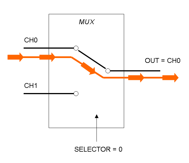
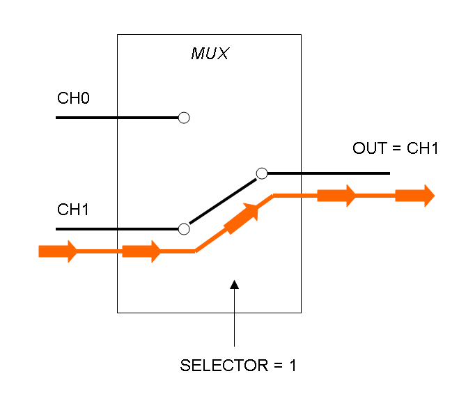
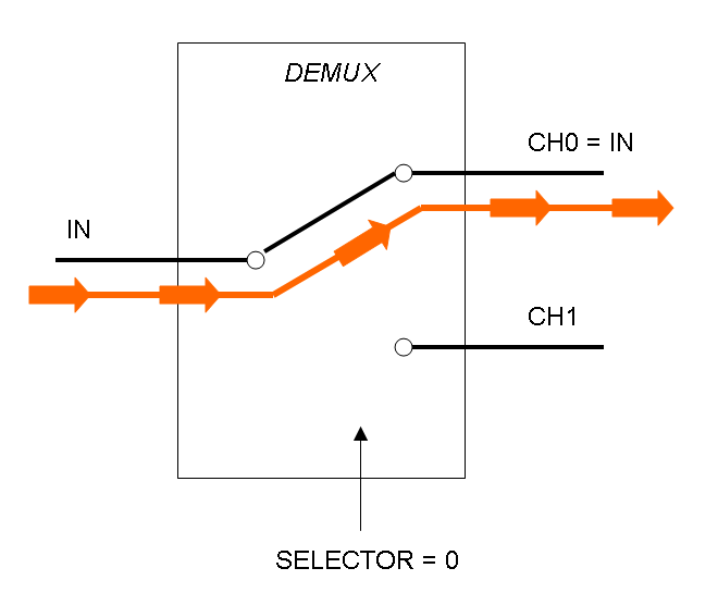
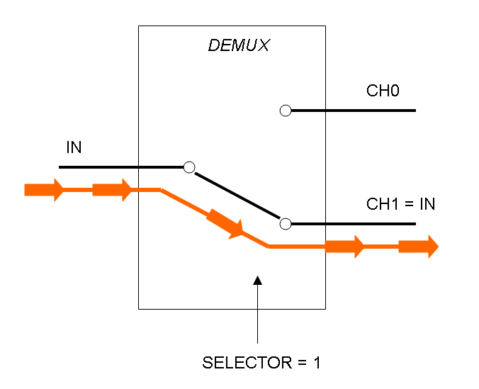
What kind of components are Mux and Demux?
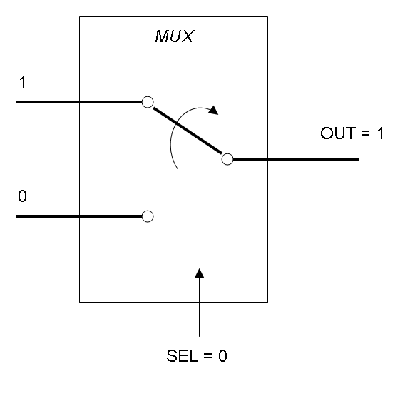
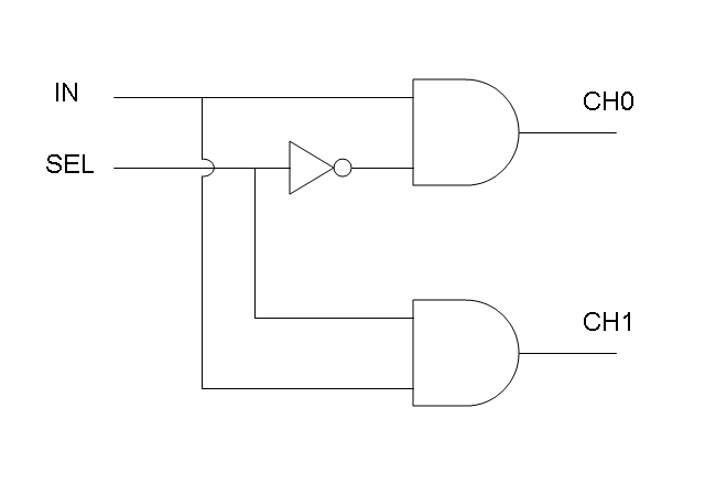
Mux is a component which conveys one of the two input channels values into a single output channel. The choice of the input channel is made by a selector.
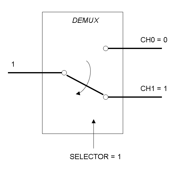
Demux is a component which conveys the only input channel value into one of the two output channels. The choice of the output channel is made by a selector.
The following pictures show data flow in Mux and Demux:
What kind of signals do we process?
In this project we consider Boolean logic signals, thus every input/output value can assume only the values 0 and 1. A function that processes Boolean values is called logic function.
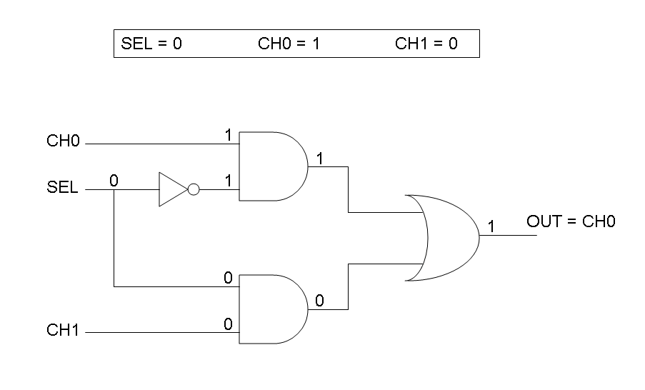
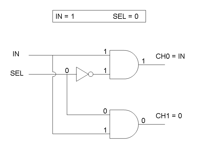
Mux and Demux can be considered by now as black boxes which implement a logic function that can process input signals to output signals. Here you can see examples of Boolean data flow in Mux and Demux:
In the following documentation we will see what is inside these black boxes.
How can we formalize Mux and Demux logic behavior?
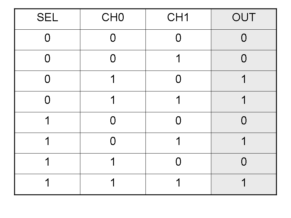
Logic functions can be formalized writing a truth table; a truth table is a mathematical table in which every row represents a combination of input values and its respective output values. The table has to be filled with every input combination.
Here you can see Mux and Demux truth tables (output columns are gray):
Building a logic circuit from a truth table
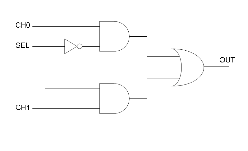
Our goal in this section is to project two logic gates networks which behave like Mux and Demux truth tables. A very useful tool to transform a truth table into a logic network is Karnaugh map.
It is possible to read about Karnaugh maps at: [http://en.wikipedia.org/wiki/Karnaugh_map]
Following Karnaugh maps method, we can write these two logic networks for Mux and Demux:
Genetic Implementation
Our goal is to mimic Mux and Demux logic networks in a biological device, such as E. coli. To perform this, we use protein/DNA and protein/protein interactions to build up biological logic gates.
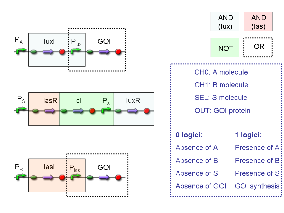
Mux and Demux logic circuits are composed by three fundamental logic gates, AND, OR, NOT: in the next paragraphs genetic implementation of these logic gates will be provided.
AND
To mimic an AND gate, we need a biological function, such as a promoter activation, which is directly turned on by the interaction between two upstream genes. In our synthetic devices, we use the luxR/luxI system: luxR can activate Plux promoter only upon 3-oxo-hexanoyl-homoserine lactone (HSL) binding; luxI generates HSL; so, only the contemporary expression of LuxR and luxI proteins can activate the downstream Plux-dependent gene expression. Another AND gate we use is the lasR/lasI system, which works in a very similar way but through another chemical intermediate, N-(3-oxododecanoyl) homoserine lactone (PAI-1).
OR
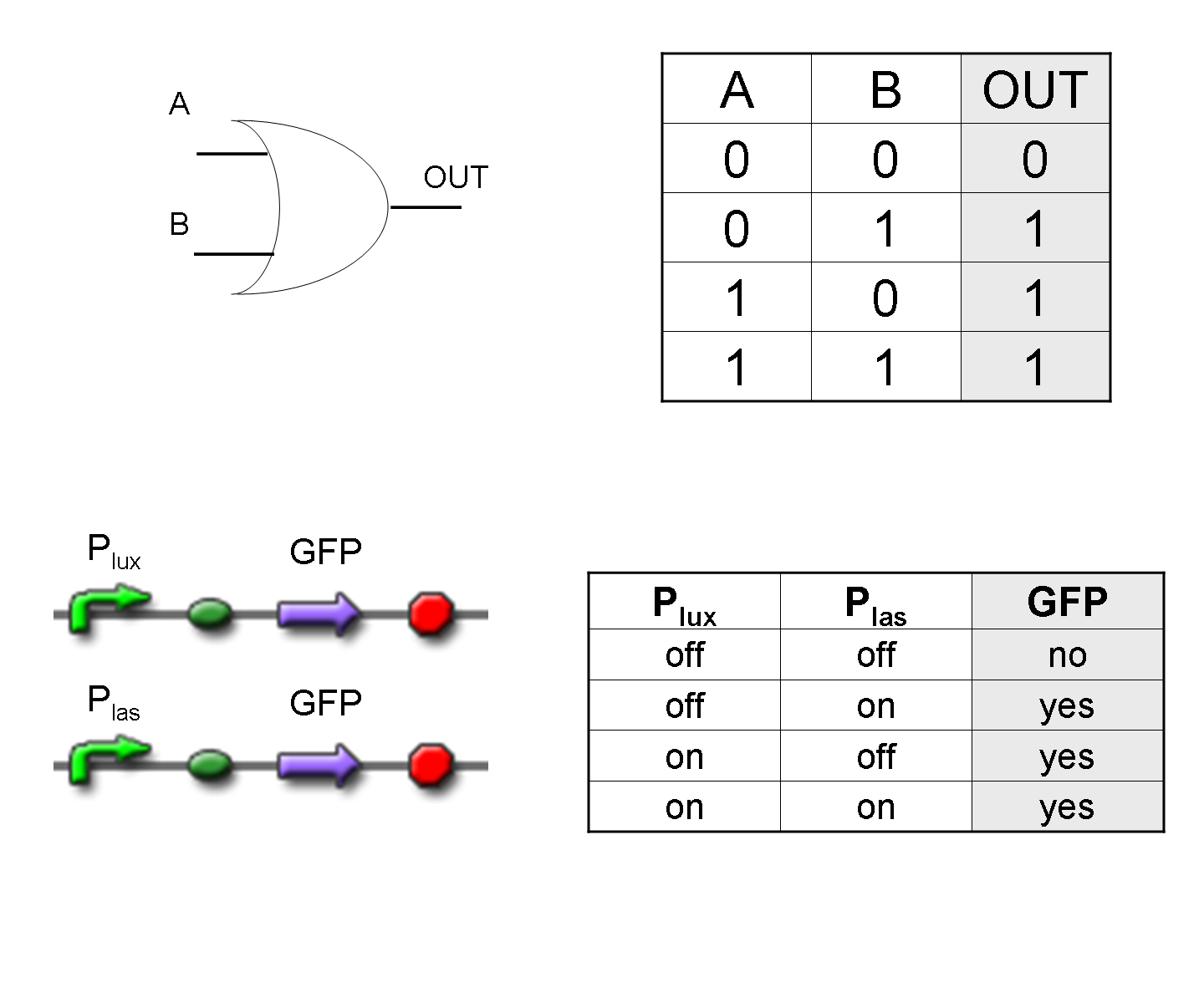
To mimic an OR gate in Mux, we need a biological function which can be activated alternatively by two independent upstream signals or by both. Thus, we combine the outputs of the upstream AND gates to assemble directly an OR reporter function, by simply repeating the reporter gene (GFP) under two different promoters (Plux and Plas). It’s sufficient to activate one of the two promoters (or both) to recover the GFP signal from engineered bacteria. There should not be an over-expression problem for GFP, in fact, in Mux device, only one promoter can be active, either Plux or Plas. Here we considered GFP output, but OR device can be generalized for every output gene.
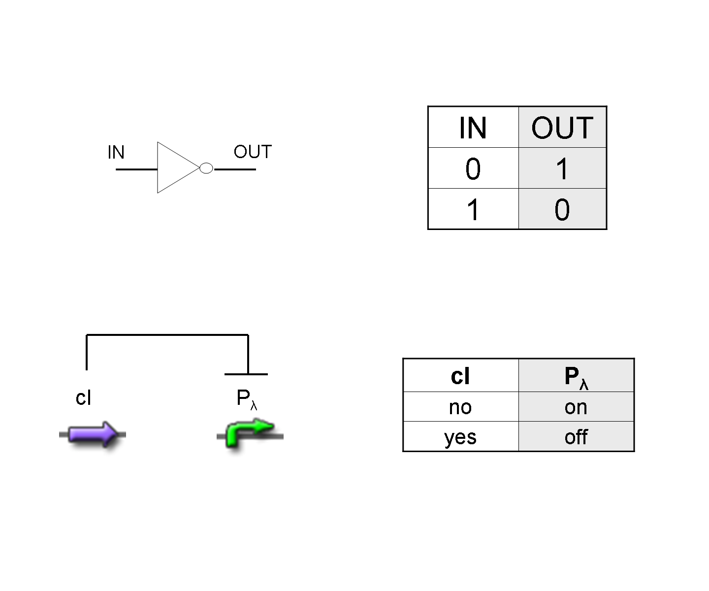
NOT
To mimic a NOT gate, we need an efficient and regulated repressor of a specific downstream promoter: in this case, we choose cI repression on Plambda, which should be specific and, upon cI inactivation, quick and efficient.
According to what above stated, genetic implementation of Mux and Demux can be obtained connecting these basic logic gates and can be summarized in this way:
Genetic Mux
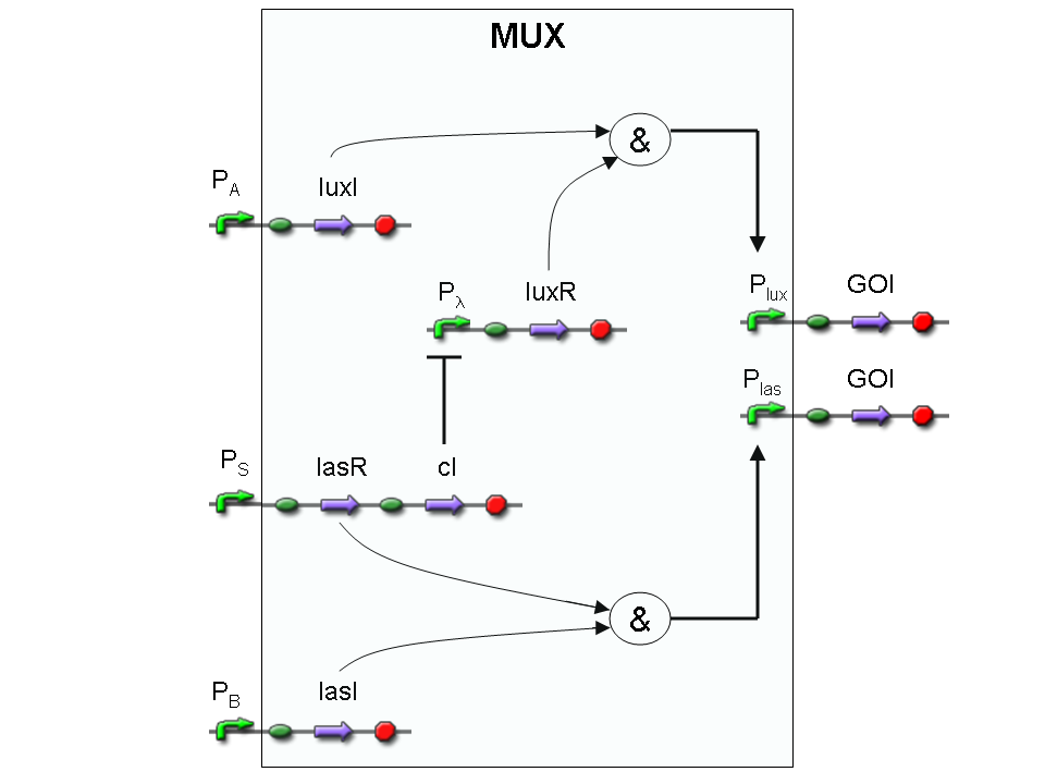
Let PA, PB and PS be three generic promoters that can be ACTIVATED respectively by the three exogenous molecules "A", "B" and "S". A genetic Mux with inputs "A" (CH0) and "B" (CH1), selector "S" and the generic protein GOI as output, can be implemented by the following gene network:
We want to supply a device that can be generalized to detect every kind of input and to express every kind of genes as output. So, input promoters and output protein generators are not part of the genetic Mux we want to build up. In this way, a hypothetical user can re-use our device assembling the desired input and output elements.
Note that the output genes are two, but, as explained in "OR" section, if the genes are identical, we can say that there is only one output; in fact, the real output is a protein synthesis and so it is not important which of the two identical genes is expressed.
However, it is possible to assemble two different genes downstream of Plux and Plas, for example two reporters. In this way, debugging process becomes easy, because we can discriminate lux system and las system activities.
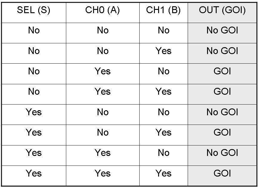
Here we report the truth table of this network:
Now we report two examples of genetic Mux behavior, in response to generic inputs.
Genetic Mux behavior - Example 1
According to Mux truth table, if "A" is not present and "B" and "S" are present, we expect to have GOI synthesis.
"A" molecule is not present, so PA promoter is not active and luxI gene is not expressed.
"B" molecule is present, so PB promoter is active and lasI gene is expressed.
"S" molecule is present, so PS promoter is active and lasR and cI genes are expressed.
cI protein represses transcription of the gene downstream of Plambda promoter, which is luxR.
lasI protein can synthesize 3-OC12-HSL. This molecule activates transcription factor lasR, which can activate Plas promoter. So, the copy of GOI gene under Plas regulation can be expressed.
The other copy of GOI gene, which is under Plux promoter regulation, is not expressed. In fact Plux is not active, because both luxI and luxR proteins are not present.
Only one of the two GOI genes is expressed, but this is sufficient to synthesize the output protein GOI.
Genetic Mux behavior - Example 2
We expect to have no GOI synthesis in response to this input combination.
"A" molecule is not present, so PA promoter is not active and luxI gene is not expressed.
"B" molecule is present, so PB promoter is active and lasI gene is expressed.
"S" molecule is not present, so PS promoter can't transcribe cI and lasR genes.
cI protein is not present, so Plambda promoter can transcribe luxR gene.
None of the two logic AND systems is active, because lux system lacks of luxI and las system lacks of lasR. So, Plux and Plas promoters are unactive and can't express GOI genes. For this reason, GOI protein is not synthesized.
These two examples show how "S" molecule can select the input to be conveyed into the single output channel: in fact its presence allows lasR expression and represses luxR expression, while "S" absence represses lasR expression and allows luxR expression.
Genetic Demux
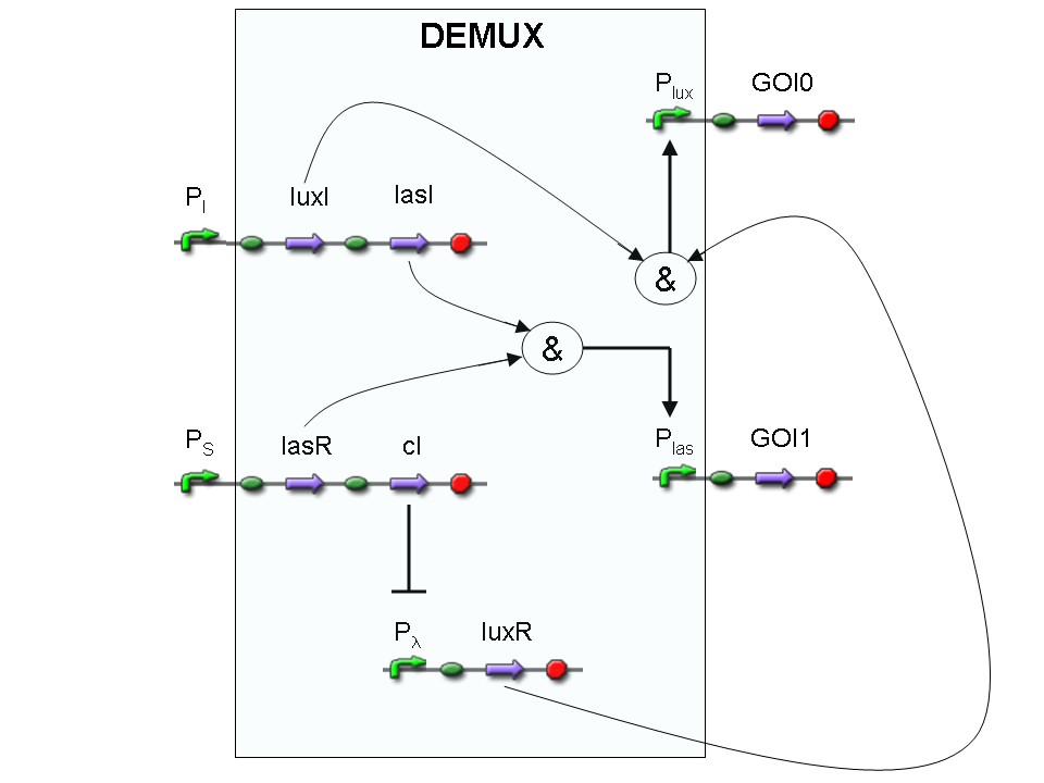
Let PI and PS be two generic promoters that can be ACTIVATED respectively by the two exogenous molecules "I" and "S". A genetic Demux with input "I", selector "S" and the generic proteins GOI0 and GOI1 as outputs (OUT0 and OUT1 respectively), can be implemented by the following gene network:
As described for genetic Mux, we want to supply a device that can be generalized to detect every kind of inputs and to express every kind of genes as output. So, input promoters and output protein generators are not part of the genetic Demux. In this way, a hypothetical user can re-use our device assembling the desired input and output elements.
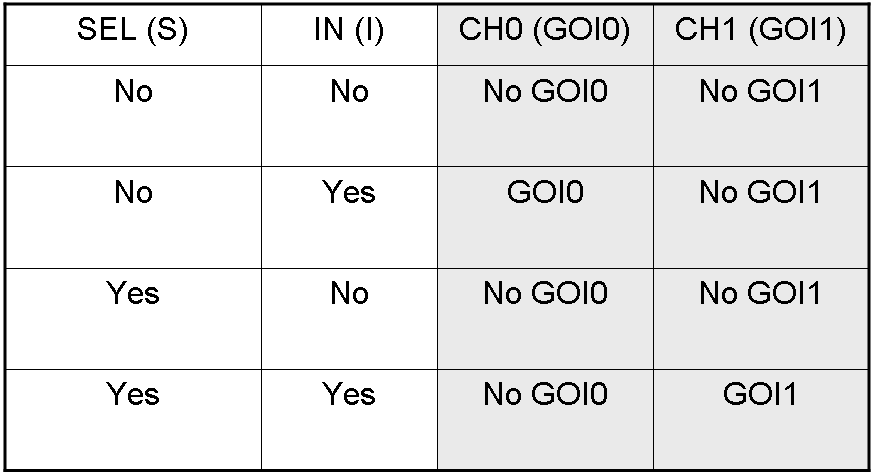
Here we report the truth table of this network:
Now we report two examples of genetic Demux behavior, in response to generic inputs.
Genetic Demux behavior - Example 1
According to Demux truth table, if "I" molecule is present and "S" molecule is absent, we expect to have GOI0 protein synthesis and no GOI1 protein synthesis.
"I" is present, so PI promoter is active and luxI and lasI genes are expressed.
"S" is not present, so PS promoter can't transcribe lasR and cI genes.
cI protein is not present, so Plambda promoter is not inhibited and luxR gene is expressed.
luxI protein can synthesize 3-OC6-HSL lactone. This molecule activates luxR transcription factor which can activate Plux promoter. In this way, GOI0 gene, which is under Plux regulation, is expressed.
On the other hand, lasI protein can synthesize 3-OC12-HSL, but lasR transcription factor is not present and so Plas promoter cannot be activated. In this way, GOI1 gene, which is under Plas regulation, is not expressed.
So, we have GOI0 protein synthesis and no GOI1 protein synthesis.
Genetic Demux behavior - Example 2
We expect to have GOI1 synthesis and no GOI0 synthesis in response to this input combination.
"I" is present, so PI promoter is active and luxI and lasI genes are expressed.
"S" is present, so PS promoter lasR and cI genes are expressed.
cI protein is present, so Plambda promoter is inhibited and luxR gene is not expressed.
lasI protein can synthesize 3-OC12-HSL lactone. This molecule activates lasR transcription factor which can activate Plas promoter. In this way, GOI1 gene, which is under Plas regulation, is expressed.
On the other hand, luxI protein can synthesize 3-OC6-HSL, but luxR transcription factor is not present and so Plux promoter cannot be activated. In this way, GOI0 gene, which is under Plux regulation, is not expressed.
So, we have GOI1 protein synthesis and no GOI0 protein synthesis.
A complete genetic Mux
In this section a complete Mux gene network is described.
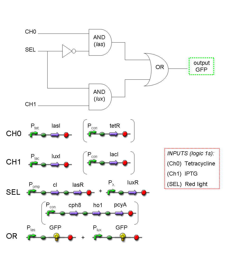
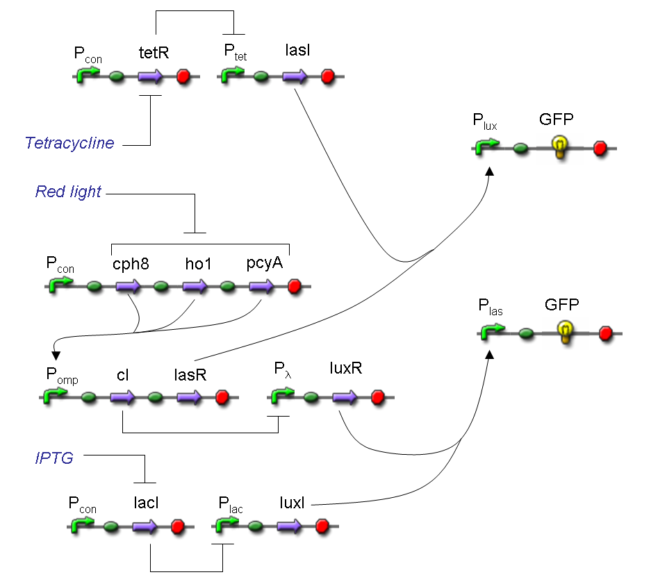
We want to build up a device in which Channel 0, Channel 1 and Selector are respectively sensitive to Tetracycline, IPTG and red light. The presence of each input corresponds to logic 1.
We chose green fluorescence as Mux output: expression of GFP corresponds to logic 1, while absence of fluorescence corresponds to logic 0.
Tetracycline and IPTG can be considered as "A" and "B" molecules, introduced in "Genetic Mux" section, because both Tetracycline and IPTG are indirect ACTIVATORS of Ptet and Plac promoters respectively.
On the other hand, red light is quite different from "S" molecule, because red light is an indirect REPRESSOR of Pomp promoter and not an activator as required by the original schema. For this reason, if we want a device in which the presence of Tetracycline, IPTG and red light correspond to logic 1, red light input should be inverted. The simplest way to do this, is to cross-exchange the two input channels. So, Tetracycline sensor (CH0) has to be assembled to las system and IPTG sensor (CH1) has to be assembled to lux system.
Complete genetic Mux - Example
According to Mux truth table, if SEL=0, CH0=1, CH1=0, output channel must be logic 1. Red light is not present, so it can't dephosphorylate cph8-ho1-pcyA complex, which is constitutively expressed. cph8-ho1-pcyA complex activates endogenous ompR, which can activate Pomp promoter, so cI and lasR genes are transcribed. cI protein binds Plambda promoter and so luxR expression is inhibited. TetR is a repressor for Ptet promoter, but Tetracycline is present, so it can bind tetR protein, which is constitutively expressed, and can activate transcription of downstream gene: lasI. Simultaneous expression of lasI and lasR can activate GFP, which is under Plas promoter. IPTG is not present, so lacI protein binds Plac promoter and represses luxI transcription.
A complete genetic Demux
In this section a complete Demux gene network is described.
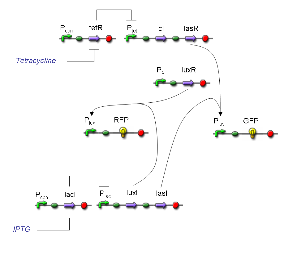
We want to build up a device in which Input and Selector are respectively IPTG and Tetracycline.
In Demux we have two output channels: red fluorescence corresponds to logic 1 at Channel 0, while green fluorescence corresponds to logic 1 at Channel 1.
Absence of reporters expression corresponds to logic 0 at Channel 0 and Channel 1.
There isn't any input combination that corresponds to logic 1 at Channel 0 and Channel 1 together.
Complete genetic Demux - Example
According to Demux truth table, if IN=1 and SEL=1, output channel 0 is logic 0 and output channel 1 is logic 1.
IPTG is present, so Plac promoter is active because IPTG binds lacI protein. This allows lasI and luxI transcription.
Tetracycline is present, so Ptet promoter is active because Tetracycline binds tetR protein. This allows cI and lasR transcription.
cI protein binds Plambda promoter and so luxR expression is inhibited.
Simultaneous expression of lasI and lasR can activate GFP, which is under Plas promoter.
There is no simultaneous expression of luxI and luxR, so RFP (which is under Plux regulation) cannot be expressed.
Final devices
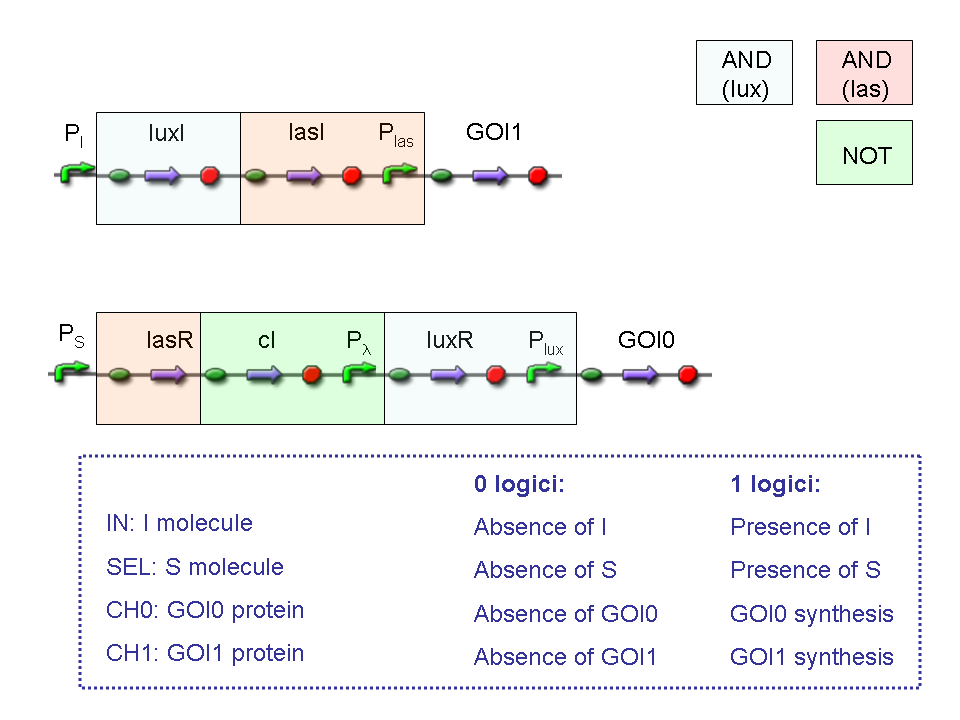
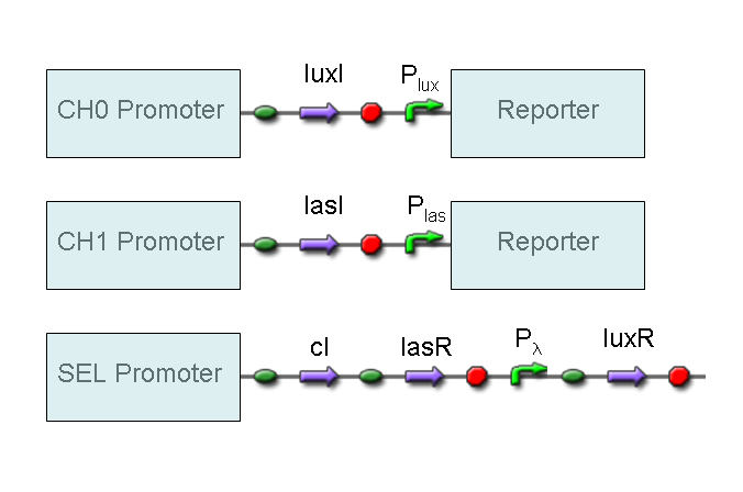
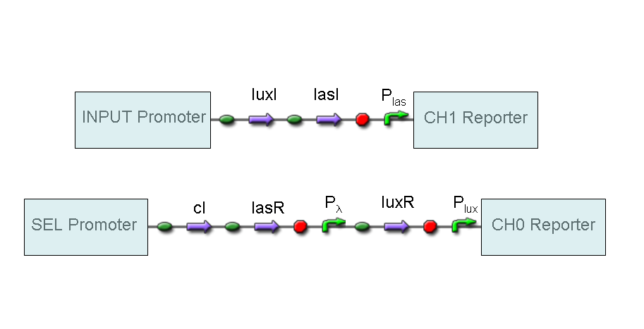
BioBrick standard parts for genetic Mux and Demux are summarized in the following schemas:
A hypothetical user of Mux or Demux has to ligate our standard parts with desired inputs and outputs, as shown in the pictures above.
The structure of our devices show that Mux and Demux systems both conform to the PoPS device boundary standard.
Applications
Mux and Demux are two fundamental devices in electronics. They are used in several applications, for example in communication devices, in Arithmetic Logic Units (ALUs), or, in general, in applications that involve channel sharing.
Analogously, they could play a crucial role in the building of complex genetic circuits. In fact, both of them can be used as controlled genetic switches.
Because our devices had been designed to be general, their application field is very wide. For example, genetic Mux can be used to integrate signals from the environment in a two-inputs and one-output biosensor; once detected, the selector controls which of the two inputs must be transferred in output. In this way, two sensing devices can be integrated in only one circuit that can compute multiplexing logic function.
On the other hand, genetic Demux can be used for controlled protein productions, where the choice of the protein to produce is made by the selector. In this case, we can imagine an industrial process where two consequent enzyme reactions are necessary to build a final product. Using a Demux, we can consider the two enzymes as system outputs and then we can easily switch on and off their production modulating selection signal.
Selector in Mux and Demux can be set manually, but also controlled automatically. In fact, it is possible to use feedback control to pilot the selector. For example, in Demux it is possible to switch the enzyme production when a specific condition (for example a pH threshold) is reached.
Switching activity in these two devices is a very powerful tool to manage multi-input and multi-output systems.
Experiments and results
Assemblies
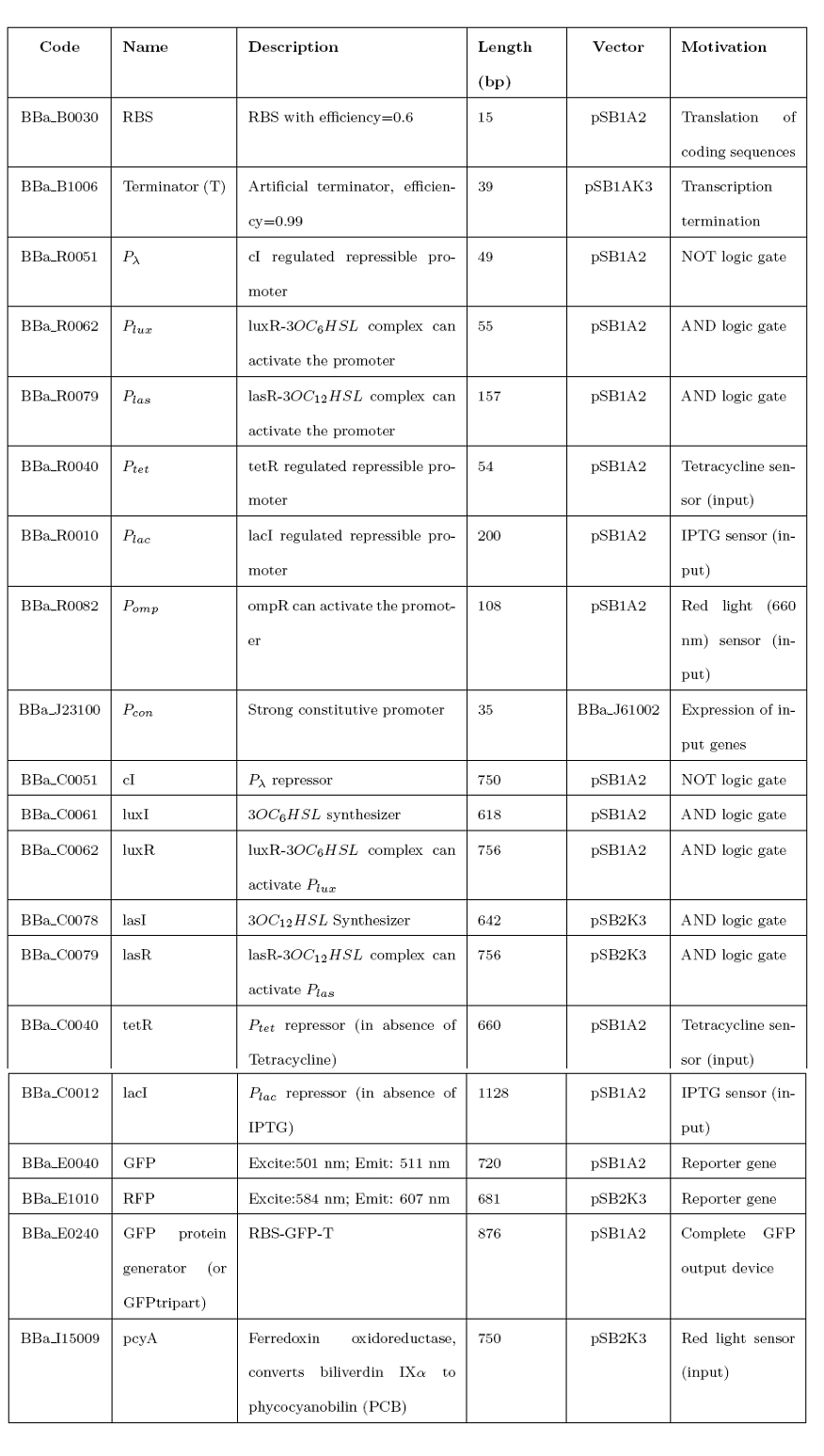
We successfully amplified the following BioBrick standard parts from Spring 2008 DNA Distribution:
while we couldn't amplify correctly the following parts:
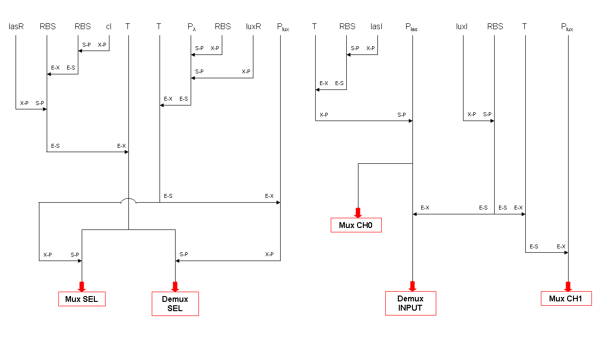
To build up our designed devices, we followed and completed this assembly tree schema:
See PARTS section for sequencing results of our assemblies.
Functional tests
We performed these boolean (on/off) fluorescence tests:
- TEST 1
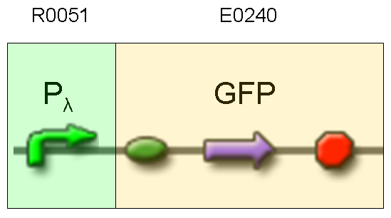
Description: we assembled an available GFP protein generator (E0240) under Plambda promoter, keeping pSB1A2 as the scaffold vector.
Motivation: cI protein was not present, so Plambda should work like a constitutive promoter. A reporter gene downstream of this promoter allows us to validate Plambda costitutive activity. That can be very useful to validate our NOT logic gate.
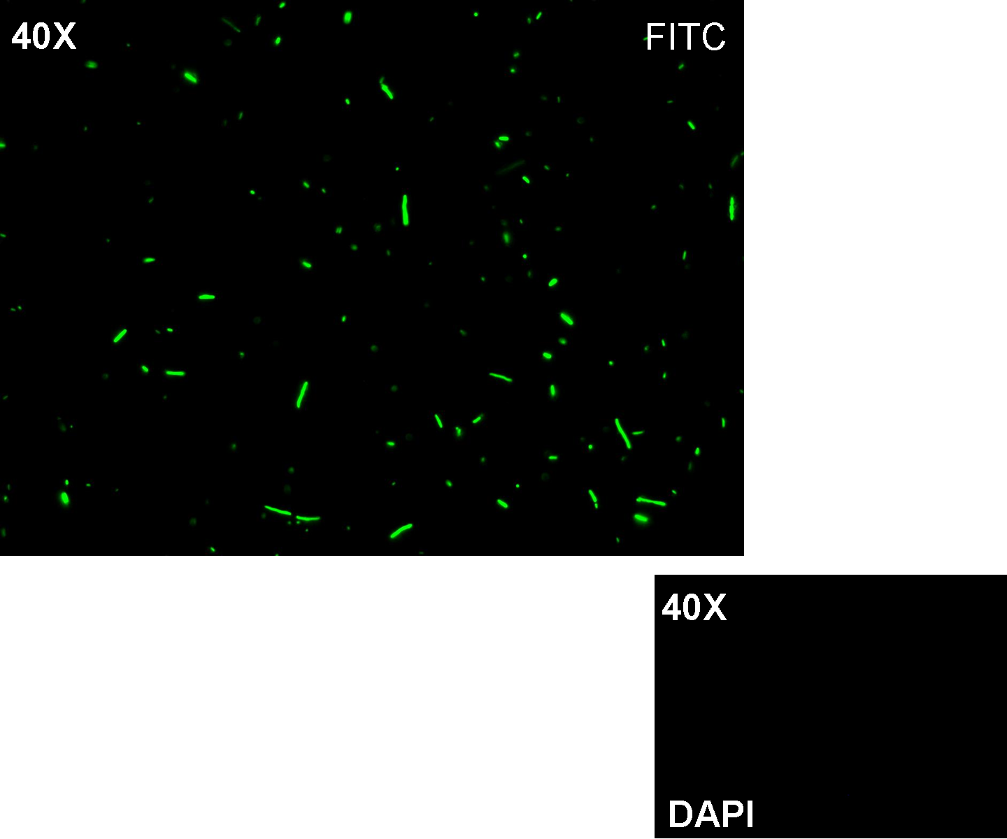
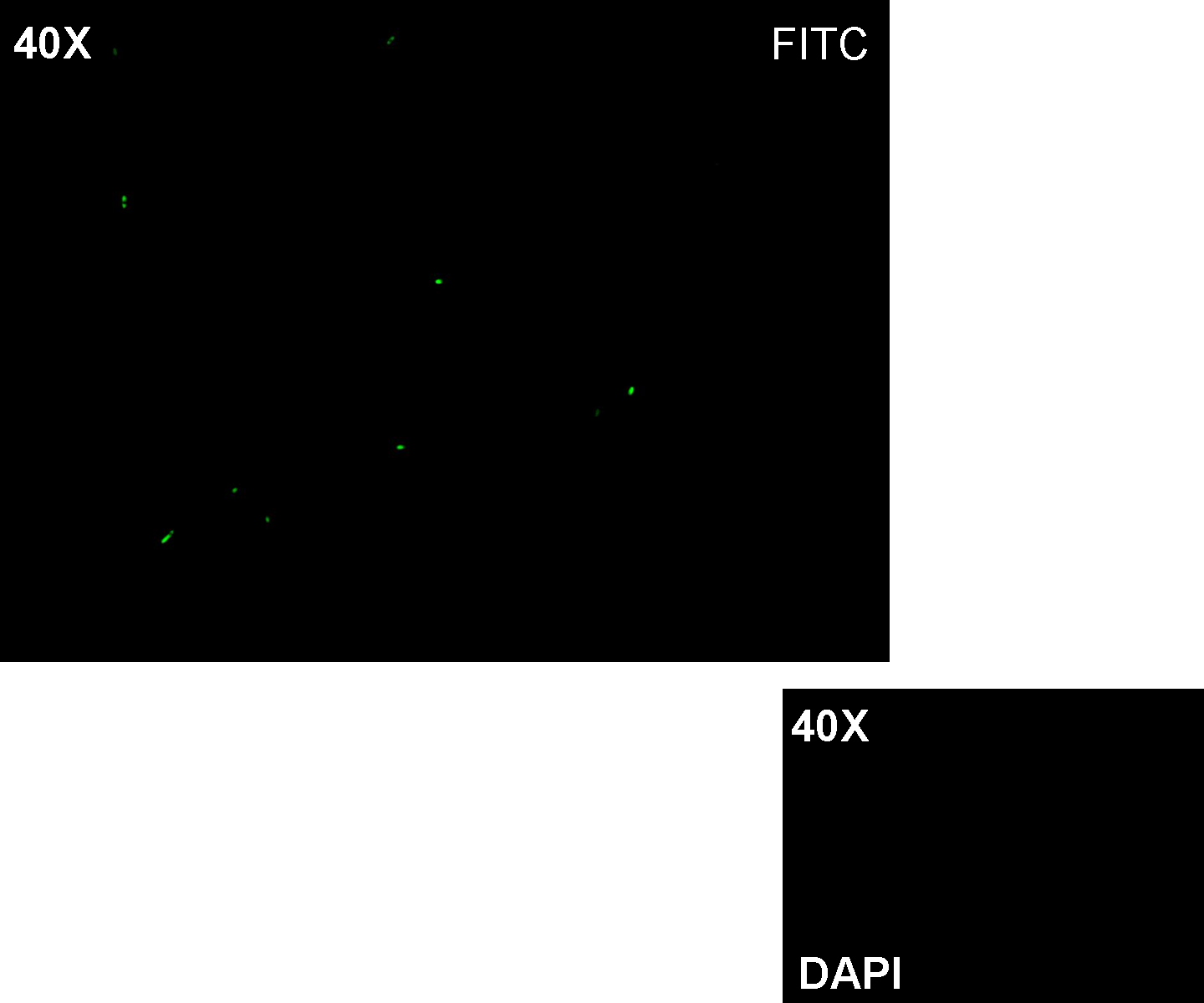
Methods: after ligation reaction of R0051 and E0240, we transformed ligation product using Invitrogen TOP10 cells and plated transformed bacteria. Then we watched the plate on the transluminator to check if positive transformants glowed under UV rays. We also picked up a fluorescent colony with a tip and infected 1 ml of LB + Amp. After 3 hours at 37°C, 220 rpm we watched 50 ul of the culture at microscope through FITC channel and DAPI channel for negative control.
Results: positive transformants glowed under UV rays and green fluorescent cells could be observed at microscope (see figure).
Comments: this experiment confirmed that GFP was expressed in positive transformants, so Plambda activity was qualitatively validated.
- TEST 2
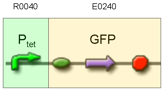
Description: we assembled E0240 under Ptet promoter, keeping pSB1A2 as the scaffold vector.
Motivation: tetR protein was not present, so Ptet should work like a constitutive promoter. A reporter gene downstream of this promoter allows us to validate Ptet costitutive activity. Ptet is useful for specific input building.
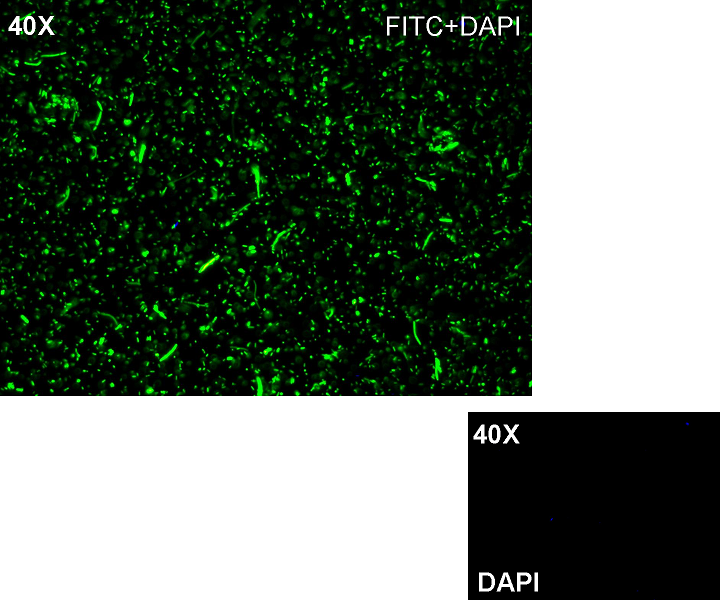
Methods: after ligation reaction of R0040 and E0240, we transformed ligation product using Invitrogen TOP10 cells and plated transformed bacteria. Then we watched the plate on the transluminator to check if positive transformants glowed under UV rays. We also picked up a fluorescent colony with a tip and infected 1 ml of LB + Amp. After 3 hours at 37°C, 220 rpm we watched 50 ul of the culture at microscope through FITC channel and DAPI channel for negative control.
Results: positive transformants glowed under UV rays and green fluorescent cells could be observed at microscope (see figure).
Comments: this experiment confirmed that GFP was expressed in positive transformants, so Ptet activity was qualitatively validated.
- TEST 3
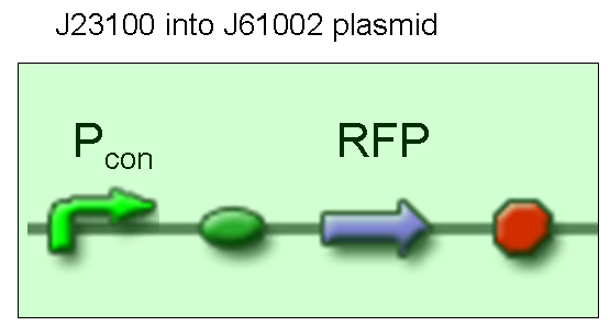
Description: we didn't perform any assembly for this experiment, because the promoter we wanted to test was contained into BBa_J61002 vector, which places a RFP protein generator between SpeI and PstI restriction sites.
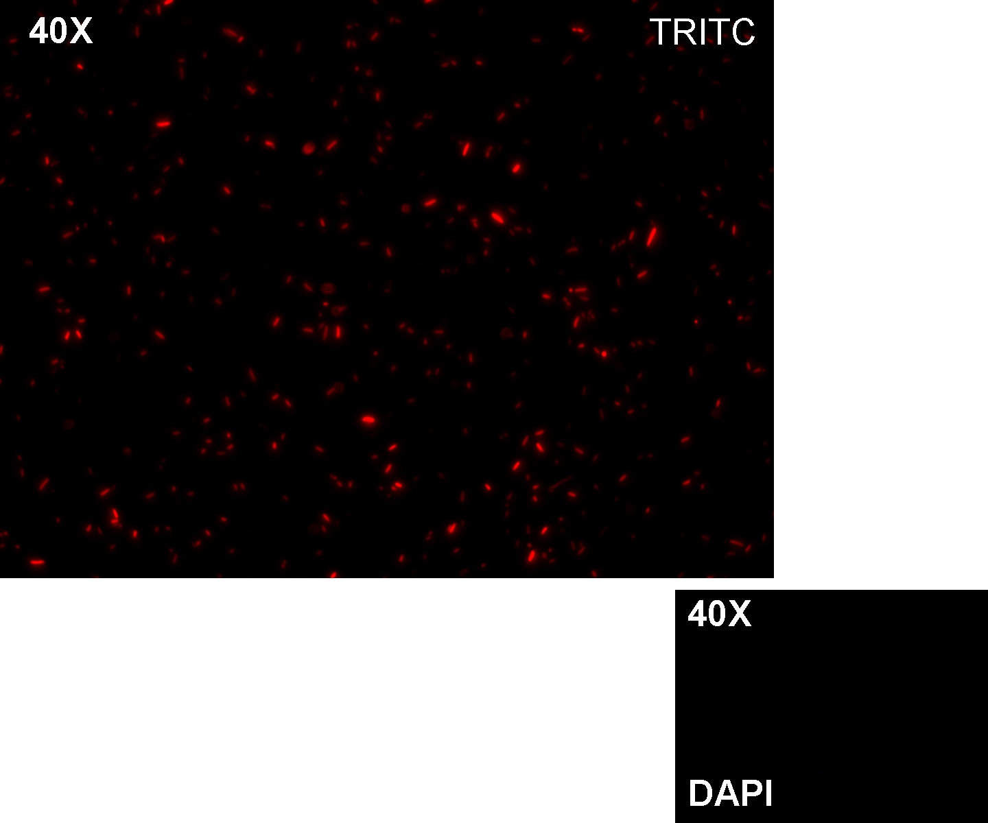
Motivation: J23100, which we call Pcon, should have a strong constitutive activity. A reporter gene downstream of this promoter allows us to validate this activity. Pcon is useful to build our inputs because some sensors like IPTG and Tetracycline sensors need the constitutive production of specific proteins, in this case lacI and tetR respectively.
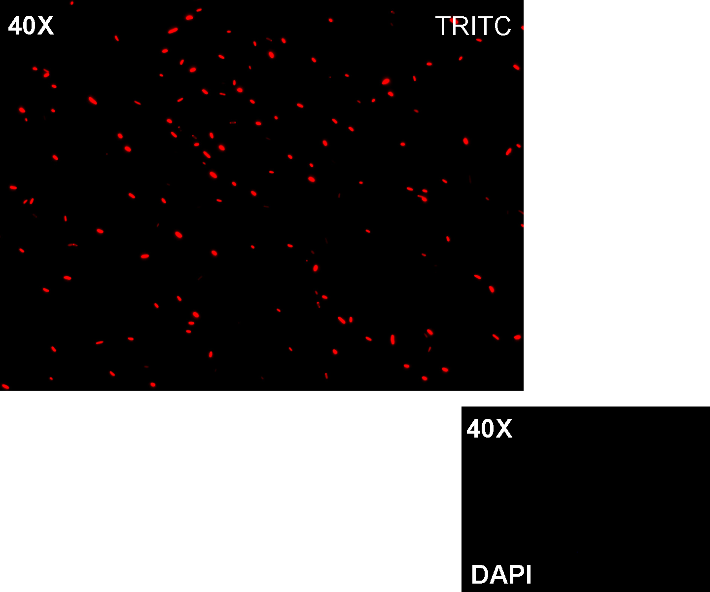
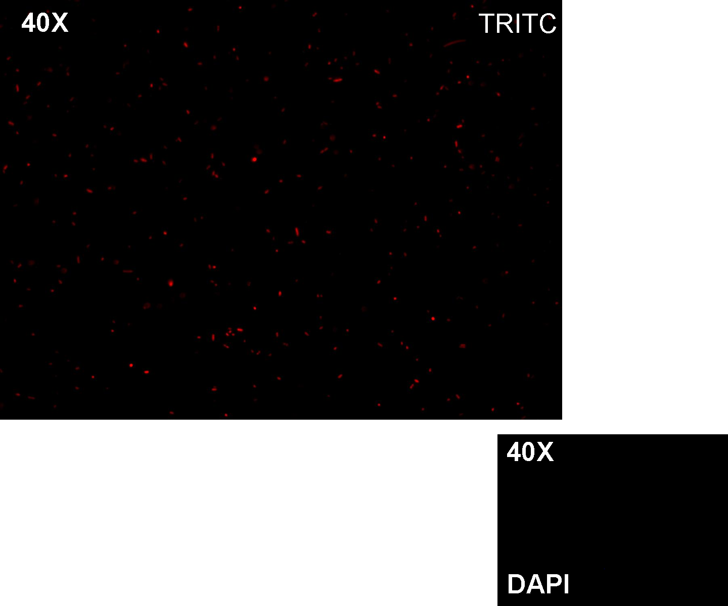
Methods we transformed J23100 using Invitrogen TOP10 and plated transformed bacteria. We expected to observe red fluorescence (using transluminator) in all the colonies. We also picked up a colony with a tip and infected 1 ml of LB + Amp. After 3 hours at 37°C, 220 rpm we watched 50 ul of the culture at microscope through TRITC channel and DAPI channel for negative control.
Results: all the grown colonies glowed under UV rays and red fluorescent cells could be observed at microscope (see figure).
Comments: this experiment confirmed that RFP was expressed in transformed bacteria, so Pcon functionality was qualitatively validated.
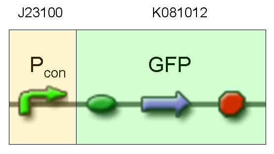
- TEST 4
Description: we assembled a constitutive promoter family member (J23100) upstream of K081012, a GFP protein generator we built. We decided to excide J23100 from its plasmid (E-S) and to open K081012 plasmid (pSB1AK3) (E-X).
Motivation: we already validated qualitatively J23100 constitutive activity, so this promoter can be used to test the GFP protein generator we built. We wanted to check if K081012 actually generates GFP.
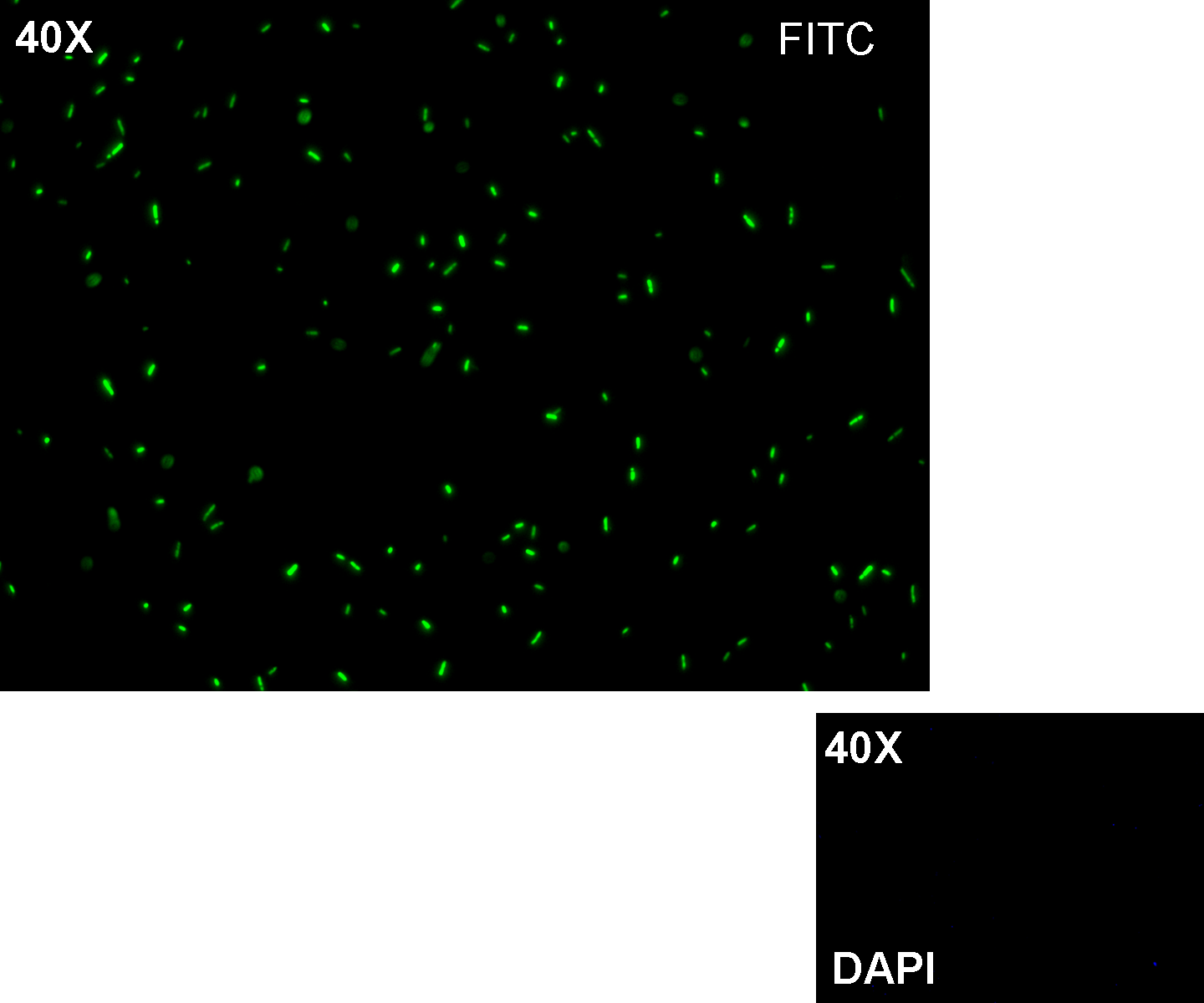
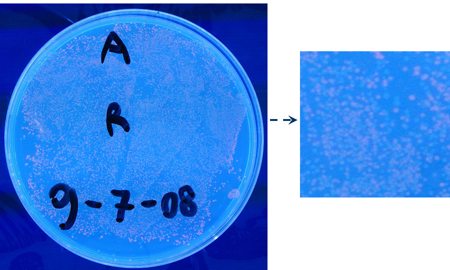
Methods after ligation reaction of J23100 and K081012, we transformed ligation product using Invitrogen TOP10 cells and plated transformed bacteria. Then we watched the plate on the transluminator to check if positive transformants glowed under UV rays. We also picked up a fluorescent colony with a tip and infected 1 ml of LB + Amp. After 3 hours at 37°C, 220 rpm we watched 50 ul of the culture at microscope through FITC channel and DAPI channel for negative control.
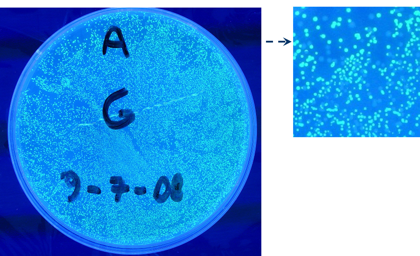
Results: positive transformants glowed under UV rays (see figure) and green fluorescent cells could be observed at microscope (see figure).
Comments: this experiment confirmed that our GFP protein generator actually generates GFP.
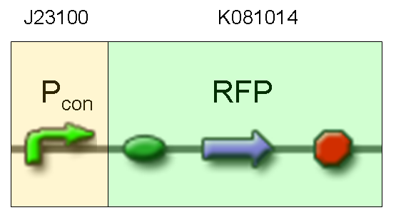
- TEST 5
Description: we assembled a constitutive promoter family member (J23100) upstream of K081014, a RFP protein generator we built. We decided to excide J23100 from its plasmid (E-S) and to open K081014 plasmid (pSB1AK3) (E-X).
Motivation: we already validated qualitatively J23100 constitutive activity, so this promoter can be used to test the RFP protein generator we built. We wanted to check if K081014 actually generates RFP.
Methods after ligation reaction of J23100 and K081014, we transformed ligation product using Invitrogen TOP10 cells and plated transformed bacteria. Then we watched the plate on the transluminator to check if positive transformants glowed under UV rays. We also picked up a fluorescent colony with a tip and infected 1 ml of LB + Amp. After 3 hours at 37°C, 220 rpm we watched 50 ul of the culture at microscope through TRITC channel and DAPI channel for negative control.
Results: positive transformants glowed under UV rays (see figure) and red fluorescent cells could be observed at microscope (see figure).
Comments: this experiment confirmed that our RFP protein generator actually generates RFP.
- TEST 6
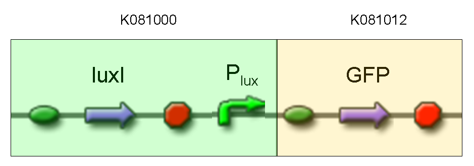
Description: we assembled K081012 (our GFP) under the Plux promoter that was contained into K081000. We kept pSB1A2 as the scaffold vector.
Motivation: we didn't assemble any input to K081000 device, so we could study only the promoter basic activity. We expected to find a weak basic activity. Plux is useful for our AND logic gate.
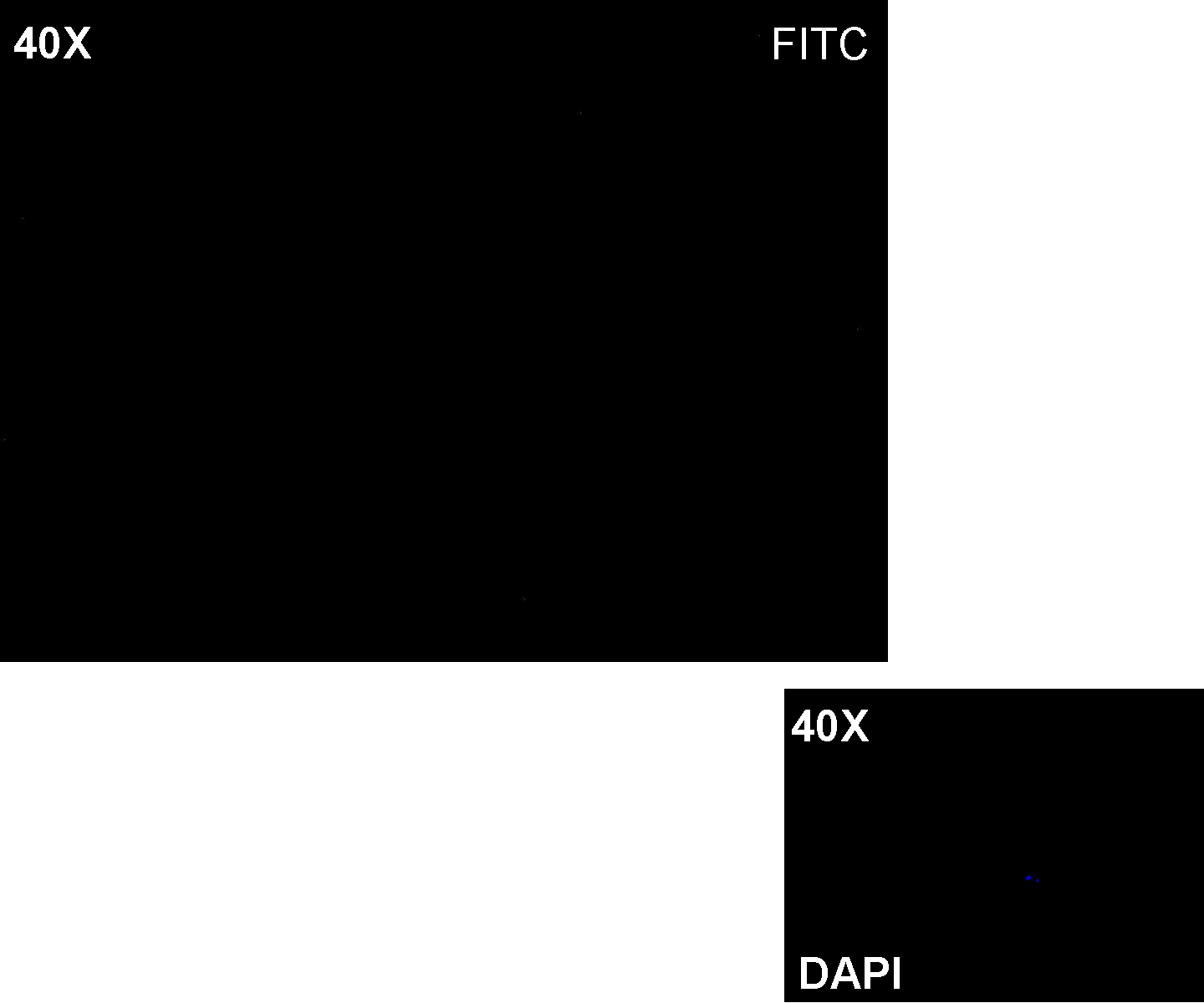
Methods: after ligation reaction of K081000 and K081012, we transformed ligation product using Invitrogen TOP10 cells and plated transformed bacteria. Then we performed a screening on 5 colonies through colony PCR to search for correctly ligated plasmid. We infected 9 ml of LB + Amp with the chosen colony and incubated the culture at 37°C, 220 rpm for 15 hours. Then we watched 50 ul of the culture at microscope through FITC channel and DAPI channel for negative control.
Results: green fluorescent cells could not be observed at microscope (see figure).
Comments: the picture above was taken using the same gain and exposition time as the previous experiments and with these parameters we cannot see any green fluorescent bacteria. Increasing exposition time, green fluorescence could be observed (picture not reported). So, we can say that GFP was expressed very weakly. This experiment confirmed that Plux promoter has a weak activity without luxI and luxR proteins.
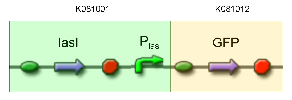
- TEST 7
Description: we assembled K081012 (our GFP) under the Plas promoter that was contained into K081001. We kept pSB1A2 as the scaffold vector.
Motivation: we didn't assemble any input to K081001 device, so we could study only the promoter basic activity. We expected to find a weak basic activity. Plas is useful for our AND logic gate.
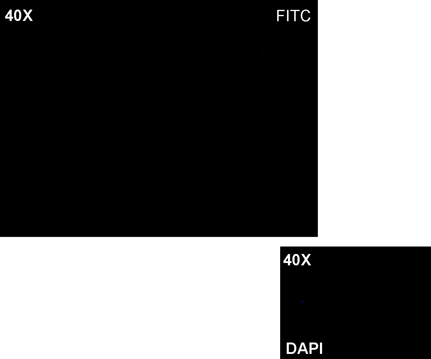
Methods: after ligation reaction of K081001 and K081012, we transformed ligation product using Invitrogen TOP10 cells and plated transformed bacteria. Then we performed a screening on 5 colonies through colony PCR to search for correctly ligated plasmid. We infected 9 ml of LB + Amp with the chosen colony and incubated the culture at 37°C, 220 rpm for 15 hours. Then we watched 50 ul of the culture at microscope through FITC channel and DAPI channel for negative control.
Results: green fluorescent cells could not be observed at microscope (see figure).
Comments: the picture above was taken using the same gain and exposition time as the previous experiments and with these parameters we cannot see any green fluorescent bacteria. Increasing exposition time, green fluorescence could be observed (picture not reported). So, we can say that GFP was expressed very weakly. This experiment confirmed that Plas promoter has a weak activity without lasI and lasR proteins.
- TEST 8
Description: we assembled K081012 (our GFP) under the Plux promoter that was contained into K081000. We also assembled K081011 upstream of K081000. We kept pSB1A2 as the scaffold vector.
Motivation: Plux promoter activity was studied in response of a constitutive expression of luxI and luxR. Plambda promoter without cI repressor guaranteed the constitutive expression of these genes. We expected to find a strong activity because Plux is turned on. lux system is useful for our AND logic gate.
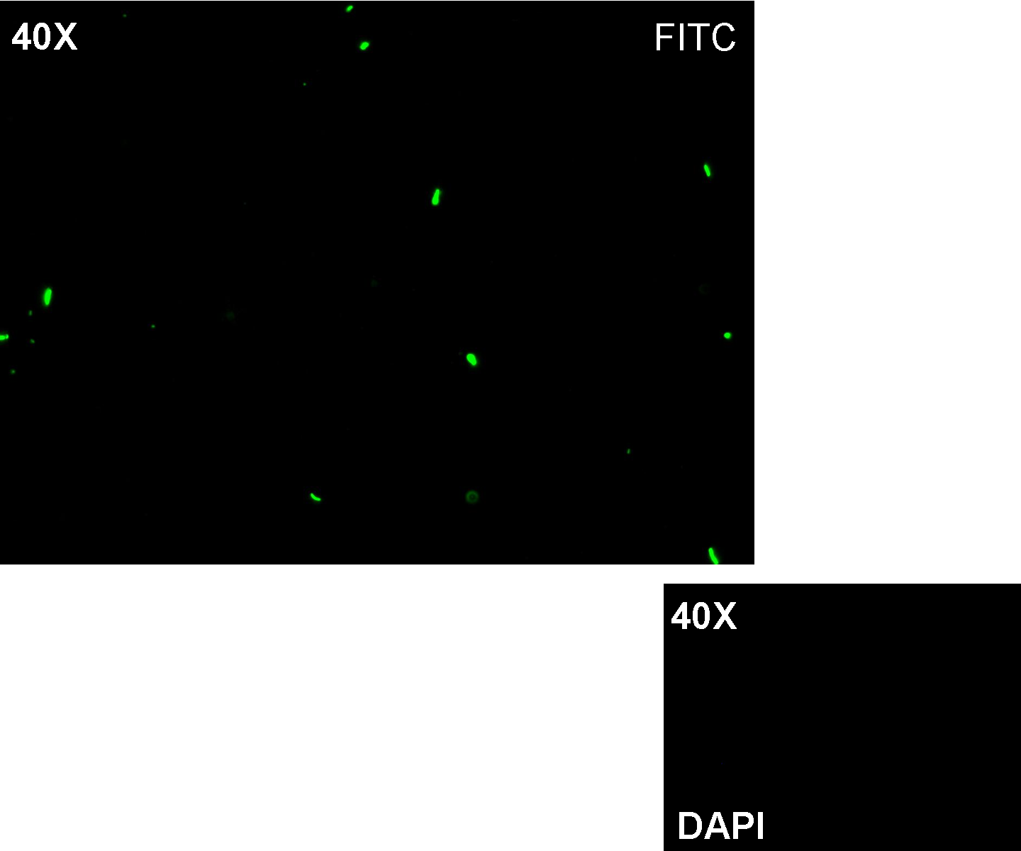
Methods: we ligated K081012 under K081000, transformed ligation, plated transformed bacteria, performed PCR screening on some colonies and extracted correctly ligated plasmids. We repeated these steps to assemble K081011 upstream of K081000-K081012, but we didn't perform PCR screening. Then we watched the plate on the transluminator to check if positive transformants glowed under UV rays. We also picked up a fluorescent colony with a tip and infected 1 ml of LB + Amp. After 3 hours at 37°C, 220 rpm we watched 50 ul of the culture at microscope through FITC channel and DAPI channel for negative control.
Results: positive transformants glowed under UV rays and green fluorescent cells could be observed at microscope (see figure).
Comments: this experiment confirmed that Plux promoter can be activated by the contemporary presence of luxI and luxR. This is a crucial result for our AND logic gate.
- TEST 9
Description: we assembled K081012 (our GFP) under the Plux promoter that was contained into K081022. We kept pSB1A2 as the scaffold vector.
Motivation: Plux promoter activity was studied in response to a constitutive expression of luxR. Plambda promoter without cI repressor guaranteed the constitutive expression of this gene. We expected to find a weak activity because luxR transcription factor is not active and so Plux cannot be turned on. We also expected to find a strong activity if we induce luxR activation using 3OC6-HSL (this is equivalent to TEST 8 conditions, because 3OC6-HSL is synthesized by luxI). lux system is useful for our AND logic gate.
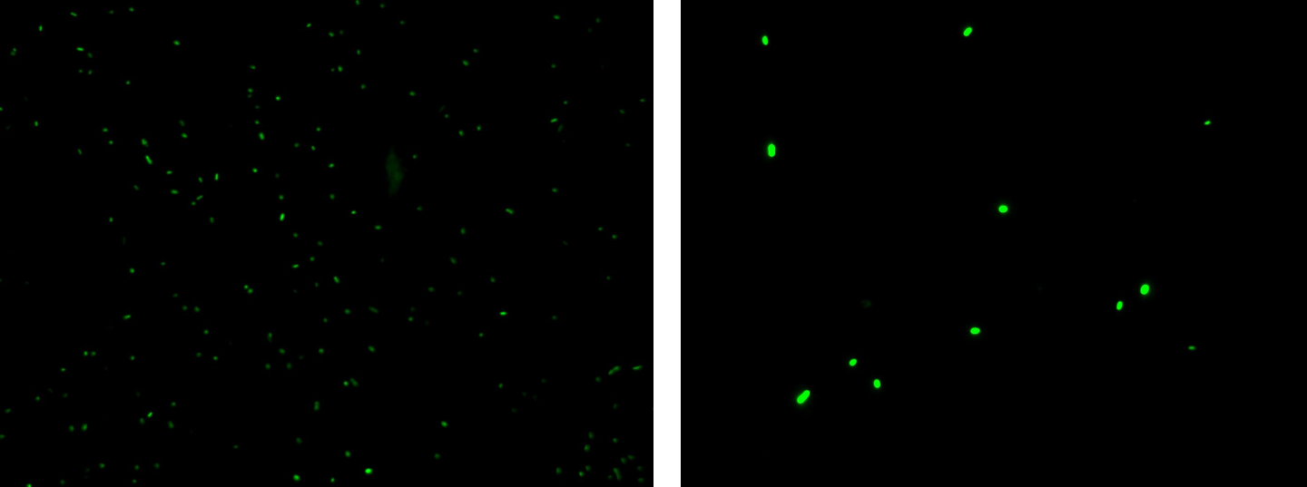
Methods: we ligated K081012 downstream of K081022, transformed ligation, plated transformed bacteria and screened three colonies to insulate a colony containing correctly ligated plasmids. We inoculated the positive colony into 9 ml of LB + Amp and incubated the culture at 37°C, 220 rpm for 15 hours. Then we diluted 1:10 the culture in two falcon tubes (5 ml cultures). One of these cultures was induced with 3OC6-HSL 1 uM. We let the two cultures grow for 2 hours and then we watched 50 ul at microscope through FITC channel and DAPI channel for negative control.
Results: green fluorescent cells could not be observed at microscope (see figure) for the non induced culture, while they could be observed for the induced culture.
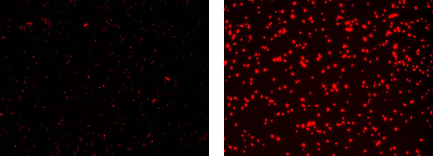
Comments: the pictures above was taken using the same gain and exposition time as the previous experiments and with these parameters we cannot see any green fluorescent bacteria for the non induced culture, while we can see green fluorescent TOP10 in the induced culture. As we wrote for TEST 6 and TEST 7, increasing exposition time green fluorescence could be observed even for the non induced culture (last picture), confirming the weak activity of Plux promoter in response of unactive luxR. This experiment confirmed that Plux promoter has a weak activity without luxI (or 3OC6-HSL) and luxR protein is not sufficient to induce a strong transcription. Adding 3OC6-HSL, luxR becomes active and so Plux is turned on.
NOTE: K081022 has a point mutation in position 349 of C0062 coding sequence. This mutation changes the aminoacid, but luxR seems to work as expected.
- TEST 10
Description: this test is equivalent to TEST 9: we assembled K081014 (our RFP) under the Plux promoter that was contained into K081004. We kept pSB1AK3 as the scaffold vector.
Motivation: we wanted to repeat TEST 9 experiment using a longer construct and a different reporter gene.
Methods: the same as TEST 9, but using K081004 instead of K081022 and using RFP (K081014) instead of GFP (K081012).
Results: red fluorescent cells could not be observed at microscope (see figure) for the non induced culture, while they could be observed for the induced culture.
Comments: the same as TEST 9.
NOTE: C0062 has the same mutation described in TEST 9. We also performed this test with an old version of K081004 carrying another point mutation (C->T at position 704 of C0062 coding sequence) that changed an aminoacid. Even in this case K081004 seemed to work as expected (results not shown).
- TEST 11
Description: we assembled K081014 (our RFP) under the artificial 39 bp terminator (B1006) that is at the end of K081022-K081012 (composite part used for TEST 9). We kept pSB1A2 as the scaffold vector.
Motivation: we wanted to test qualitatively if our terminator actually stops transcription.
Methods: we assembled K081014 downstream of K081022, transformed ligation, plated transformed bacteria and insulated a colony containing correctly ligated plasmid. We inoculated the colony into 9 ml of LB + Amp and incubated the culture at 37°C, 220 rpm for 15 hours. Then we diluted 1:10 the culture in two falcon tubes (5 ml cultures). One of these cultures was induced with 3OC6-HSL 1 uM. We let the two cultures grow for 2 hours and then we watched 50 ul at microscope through FITC channel (positive control), TRITC channel and DAPI channel (negative control).
Results: soon
Comments: soon
We also performed these quantitative fluorescence tests:
- TEST A
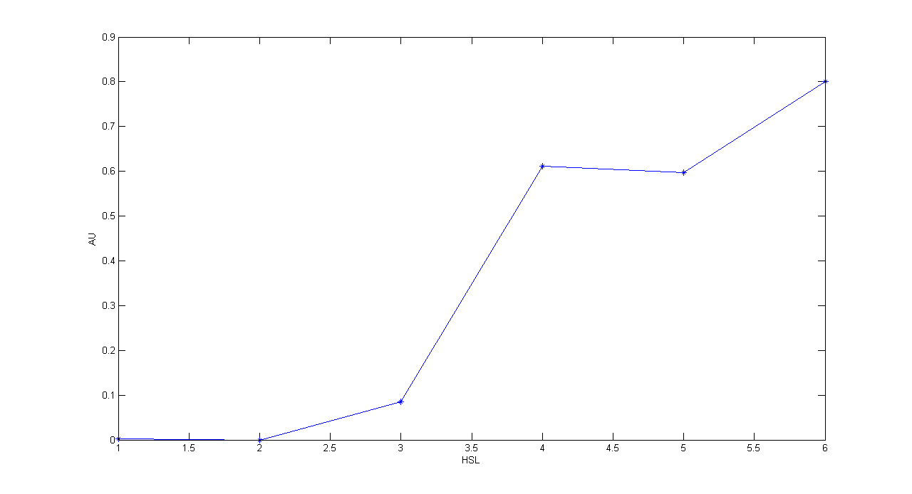
Description: this test is an extension of TEST 9. We induced six cultures with 3OC6-HSL at different concentrations to study quantitatively HSL-GFP static transfer function.
Motivation: we want to know cutoff point of this device.
Methods: the same as TEST 9, but we diluted the overnight 9 ml culture 1:10 in six falcon tubes (5 ml cultures). We induced the six cultures with 3OC6-HSL 0 nM, 0.1 nM, 1 nM, 10 nM, 100 nM and 1 uM respectively. We incubated the cultures at 37°C, 220 rpm for 2 hours and then we watched 50 ul at microscope through FITC channel and DAPI channel for negative control. We prepared two 50 ul glasses for each culture. We acquired three frames at 2.5 s (maximum exposition time) and 10 ms exposition time for every sample. We used ImageJ software to count automatically the number of cells for every frame. Then we computed n10/n2.5 (where n is the number of cells) to calculate the percentage of cells that glowed in the 10 ms acquisition, assuming that in the 2.5 s acquisition we can see the total number of cells. For each HSL concentration, we calculated the mean value of the 6 statistics (3 frames for each of the 2 glasses).
Results:
Comments: we computed the statistic n10/n2.5 because we know that when fluorescence is weak, cells cannot be seen at low exposition times. So, we calculate the ratio between the cells we can see at a low exposition time and the total number of cells in the frame. We chose 10 ms because the previous experiments with GFP had been performed using this parameter. We know that this is not an exact statistic, in fact we have to consider the count errors of ImageJ software, especially when cells are superimposed. Further quantitative experiments will have to be performed using standard measurement, in order to characterize parts.
- TEST B
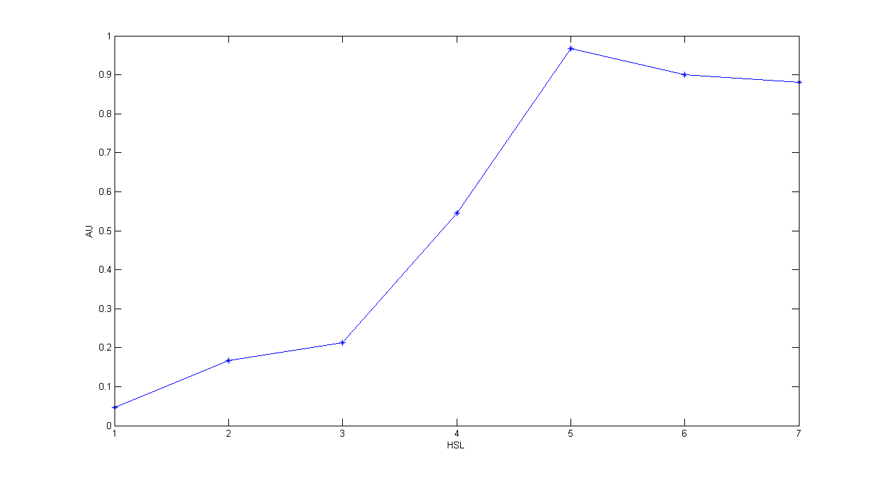
Description: this test is an extension of TEST 10. We induced seven cultures with 3OC6-HSL at different concentrations to study quantitatively HSL-RFP static transfer function.
Motivation: we want to know cutoff point of this device.
Methods: the same as TEST 10, but we diluted the overnight 9 ml culture 1:10 in seven falcon tubes (5 ml cultures). We induced the seven cultures with 3OC6-HSL 0 nM, 0.1 nM, 1 nM, 10 nM, 100 nM, 1 uM and 10 uM respectively. We incubated the cultures at 37°C, 220 rpm for 2 hours and then we watched 50 ul at microscope through TRITC channel and DAPI channel for negative control. We prepared two 50 ul glasses for each culture. We acquired three frames at 2.5 s (maximum exposition time) and 90 ms exposition time for every sample. We used ImageJ software to count automatically the number of cells for every acquisition. Then we computed n90/n2.5 (where n is the number of cells) to calculate the percentage of cells that glowed in the 90 ms acquisition, assuming that in the 2.5 s acquisition we can see the total number of cells. For each HSL concentration, we calculated the mean value of the 6 statistics (3 frames for each of the 2 glasses).
Results:
Comments: we computed the statistic n90/n2.5 because we know that when fluorescence is weak, cells cannot be seen at low exposition times. So, we calculate the ratio between the cells we can see at a low exposition time and the total number of cells in the frame. We chose 90 ms because the previous experiments with RFP had been performed using this parameter. We know that this is not an exact statistic, in fact we have to consider the count errors of ImageJ software, especially when cells are superimposed. As we wrote for TEST 9, further quantitative experiments will have to be performed using standard measurement, in order to characterize parts.
Conclusions
All the experiments we performed were consistent with our expectations.
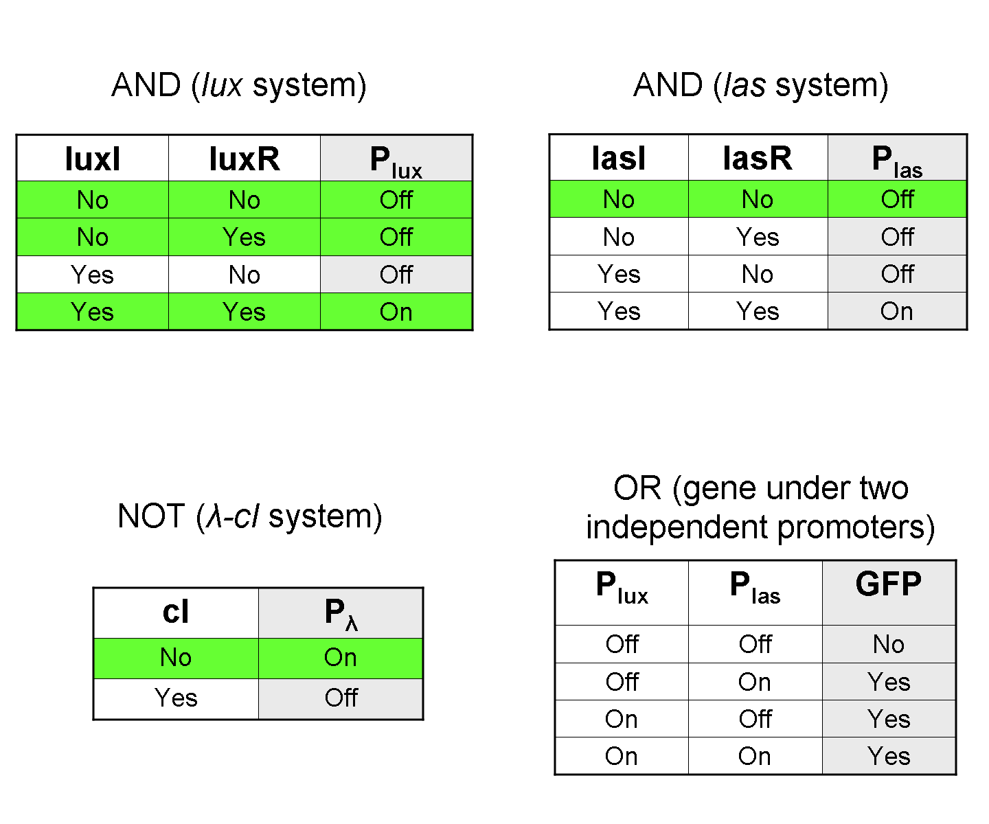
Considering the elementary logic gates of our final devices (AND, OR, NOT), we validated some truth table rows:
In particular:
- TEST 1 validated the first row of NOT logic gate.
- TEST 6 validated the first row of AND (lux) logic gate.
- TEST 7 validated the first row of AND (las) logic gate.
- TEST 8, TEST 9 (with induction) and TEST 10 (with induction) validated the fourth row of AND (lux) logic gate.
- TEST 9 (without induction) and TEST 10 (without induction) validated the second row of AND (lux) logic gate.
 "
"
