Team:Harvard/Dailybook/Week1/Widgetry
From 2008.igem.org
(Difference between revisions)
(New page: =Monday: June 23, 2008= ==Lab== * Received ordered parts from McMaster-Carr * Drew preliminary designs for MFC 300px * Cut polycarbonate tubing ** 2" Square T...) |
|||
| Line 3: | Line 3: | ||
* Received ordered parts from McMaster-Carr | * Received ordered parts from McMaster-Carr | ||
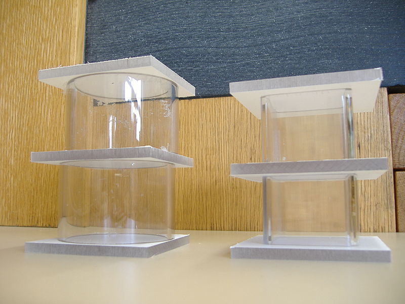
* Drew preliminary designs for MFC | * Drew preliminary designs for MFC | ||
| - | [[Image:Mfc_prototype1.jpg|300px]] | + | [[Image:800px-Mfc_prototype1.jpg|300px]] |
* Cut polycarbonate tubing | * Cut polycarbonate tubing | ||
** 2" Square Tubing: | ** 2" Square Tubing: | ||
| Line 14: | Line 14: | ||
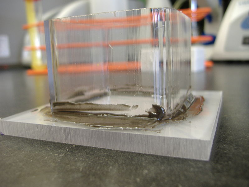
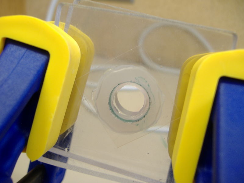
* Tested 5 minute epoxy: | * Tested 5 minute epoxy: | ||
** Attached 1.5" (2" Diameter) polycarbonate square tubing to sheet | ** Attached 1.5" (2" Diameter) polycarbonate square tubing to sheet | ||
| - | [[Image:Mfc_epoxy.JPG|300px]] | + | [[Image:800px-Mfc_epoxy.JPG|300px]] |
* Tested silicon: | * Tested silicon: | ||
** Attached 1.5" (2" Diameter) polycarbonate square tubing to sheet | ** Attached 1.5" (2" Diameter) polycarbonate square tubing to sheet | ||
| - | [[Image:Mfc_silicon.JPG|300px]] | + | [[Image:800px-Mfc_silicon.JPG|300px]] |
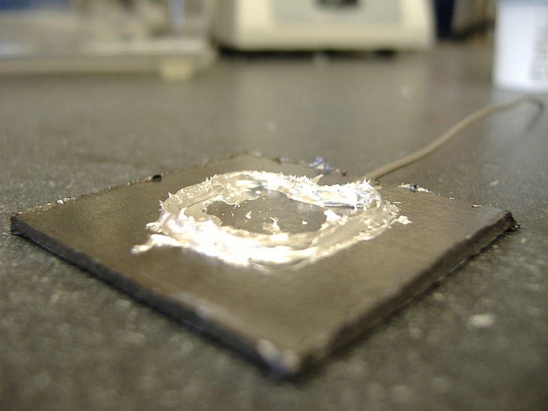
* Tested silver epoxy: | * Tested silver epoxy: | ||
** Attached titanium wire to graphite sheet | ** Attached titanium wire to graphite sheet | ||
| - | [[Image:Mfc_silverepoxy.JPG|300px]] | + | [[Image:800px-Mfc_silverepoxy.JPG|300px]] |
==Results== | ==Results== | ||
| Line 75: | Line 75: | ||
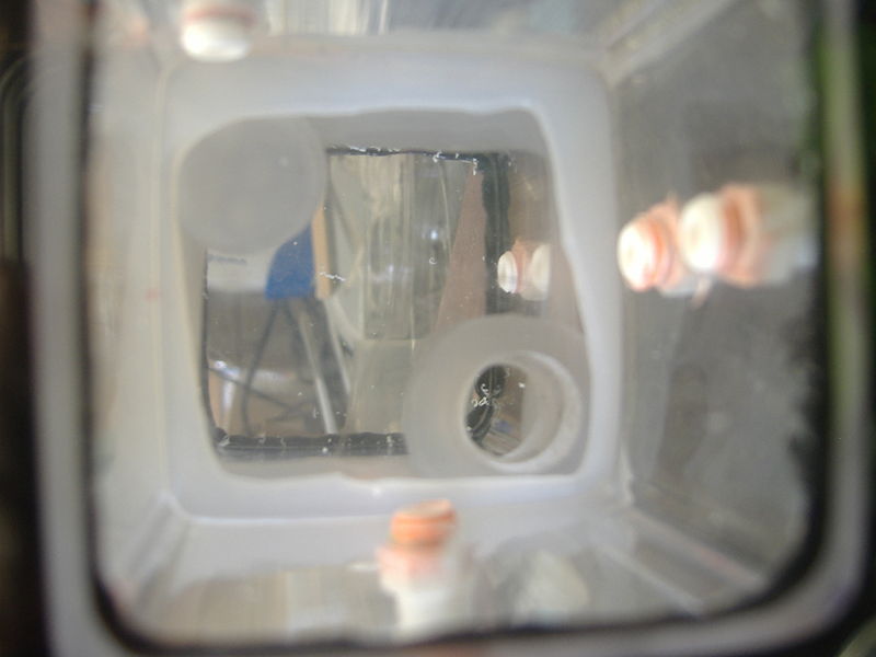
*Milled holes for injection ports and bolts | *Milled holes for injection ports and bolts | ||
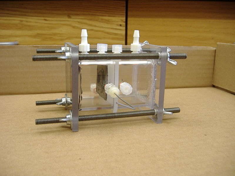
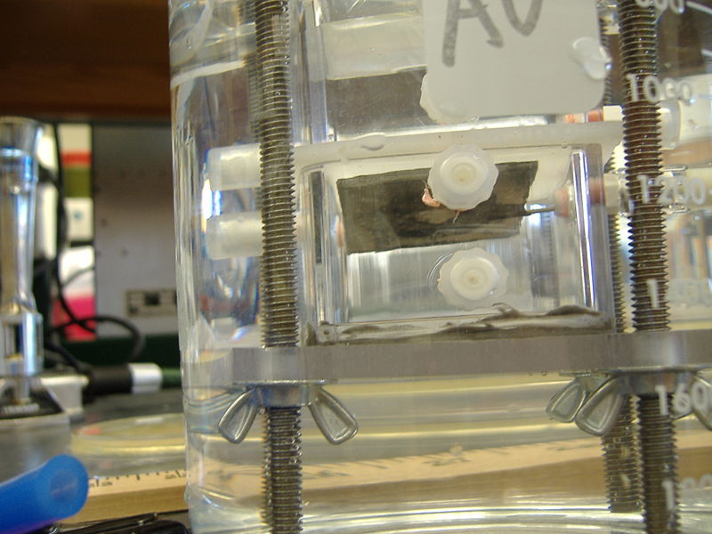
*Assembled prototype for MFC minus anode and membrane | *Assembled prototype for MFC minus anode and membrane | ||
| - | [[Image:Mfc_prototype2.JPG|300px]] | + | [[Image:800px-Mfc_prototype2.JPG|300px]] |
*Make cathode using alternative wiring design to maximize surface area | *Make cathode using alternative wiring design to maximize surface area | ||
*Made another chamber using epoxy for autoclave test | *Made another chamber using epoxy for autoclave test | ||
*Airtight test by submerging pressurized MFC prototype in water | *Airtight test by submerging pressurized MFC prototype in water | ||
** No air bubbles observed | ** No air bubbles observed | ||
| - | [[Image:Mfc_oxygentest.JPG|300px]] | + | [[Image:800px-Mfc_oxygentest.JPG|300px]] |
==Purchased== | ==Purchased== | ||
| Line 142: | Line 142: | ||
**added nafion membrane | **added nafion membrane | ||
**added carbon felt anode | **added carbon felt anode | ||
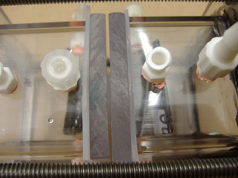
| - | [[Image:Mfc_prototype3.JPG|300px]] | + | [[Image:800px-Mfc_prototype3.JPG|300px]] |
*membrane did not pass water-tight test | *membrane did not pass water-tight test | ||
| Line 150: | Line 150: | ||
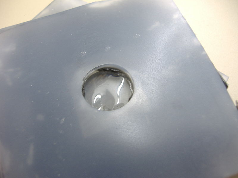
'''''Warped membrane''''' | '''''Warped membrane''''' | ||
| - | [[Image:Mfc_nafionwarped.JPG|300px]] | + | [[Image:800px-Mfc_nafionwarped.JPG|300px]] |
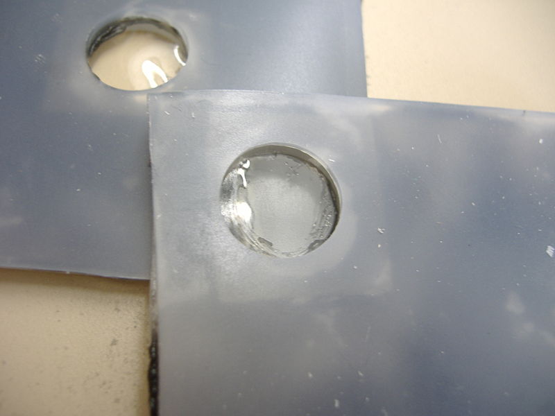
'''''Normal membrane''''' | '''''Normal membrane''''' | ||
| - | [[Image:Mfc_nafionnormal.JPG|300px]] | + | [[Image:800px-Mfc_nafionnormal.JPG|300px]] |
* new MFC: | * new MFC: | ||
| Line 167: | Line 167: | ||
***outer “ring” | ***outer “ring” | ||
***cathode chamber | ***cathode chamber | ||
| - | [[Image:Mfc_prototype4.JPG|300px]] | + | [[Image:800px-Mfc_prototype4.JPG|300px]] |
:* water tight test: | :* water tight test: | ||
:** passed water tight test | :** passed water tight test | ||
| Line 179: | Line 179: | ||
==Lab== | ==Lab== | ||
*Finished building air cathode MFC, minus injection ports | *Finished building air cathode MFC, minus injection ports | ||
| - | [[Image:Mfc_airprototype.JPG|300 px]] | + | [[Image:800px-Mfc_airprototype.JPG|300 px]] |
*Autoclaved LML | *Autoclaved LML | ||
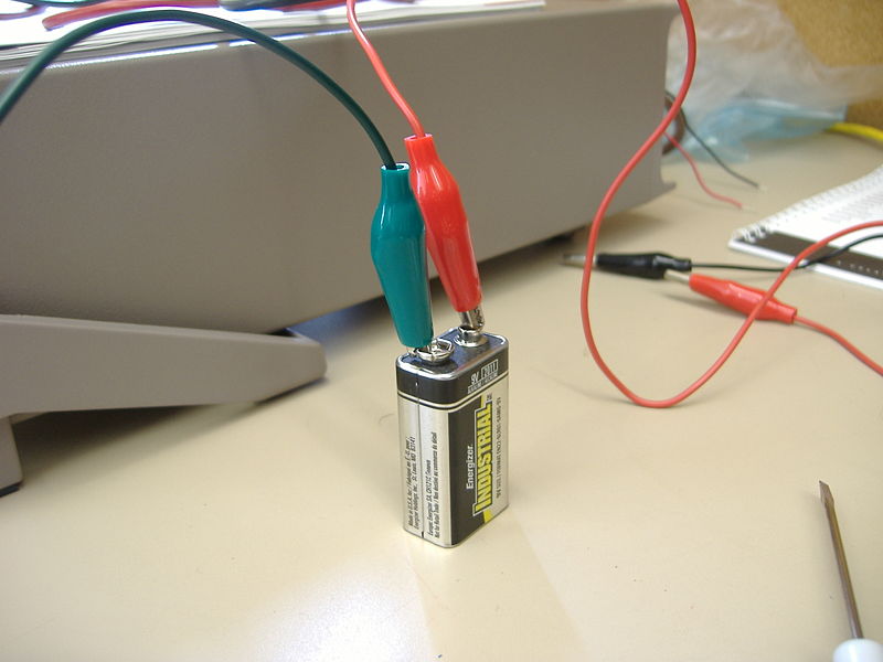
=== Keithley test === | === Keithley test === | ||
| - | [[Image:Mfc_circuit.JPG|300px]] | + | [[Image:800px-Mfc_circuit.JPG|300px]] |
* Connected simple battery-resistor circuit to both 2700 alone and with 7700 switching module | * Connected simple battery-resistor circuit to both 2700 alone and with 7700 switching module | ||
** Used 8.78 V source of 4M ohm resistance with 1% accuracy | ** Used 8.78 V source of 4M ohm resistance with 1% accuracy | ||
Latest revision as of 17:49, 28 October 2008
Contents |
Monday: June 23, 2008
Lab
- Received ordered parts from McMaster-Carr
- Drew preliminary designs for MFC
- Cut polycarbonate tubing
- 2" Square Tubing:
- Three 1.5" sections
- Two 3" sections
- 3" Round Tubing:
- Four 2" sections
- Polycarbonate sheets:
- Four 3x3" squares
- 2" Square Tubing:
- Tested 5 minute epoxy:
- Attached 1.5" (2" Diameter) polycarbonate square tubing to sheet
- Tested silicon:
- Attached 1.5" (2" Diameter) polycarbonate square tubing to sheet
- Tested silver epoxy:
- Attached titanium wire to graphite sheet
Results
Silicon
- questionable adhesiveness
Epoxy
- fairly strong adhesiveness
Silver epoxy
Resistances:
- Wire : 0.35 Ω / in
- Graphite: 1 Ω / in
- Across junction: 5 Ω / in
Purchased
From McMaster-Carr
| Qty. | Part |
| 20ft | High-Temperature Silicone Rubber Tubing Soft, 3/16" ID, 3/8" OD, 3/32" Wall, Blue |
| 20ft | High-Temperature Silicone Rubber Tubing Soft, 3/16" ID, 3/8" OD, 3/32" Wall, White |
| 3 (packs of 10) | Aluminum Oxide Cloth Sanding Sheet 280 Grit, 9" X 11" |
| 1 | Bright Finish High-Speed Stl Spiral Point Tap 1/4"-28, H3 Pitch Diameter, 2 Flute |
| 2 (packs of 10) | Plain Steel Fully Threaded Stud 1/4"-20 Thread, 6" Length |
| 3 (packs of 25) | Zinc Alloy Wing Flange Nut 1/4"-20 Screw Size, 1" Wing Spread |
Tuesday: June 24, 2008
Meeting with Peter Girguis
General Design
- Three basic designs:
- Vertical with two chambers stacked
- Vertical with anode and air cathode below
- Horizontal (perhaps with incline)
- Nitrogen/Oxygen bubbling
- Maybe do in flasks outside of actual fuel cell
Lab
- Milled holes for injection ports and bolts
- Assembled prototype for MFC minus anode and membrane
- Make cathode using alternative wiring design to maximize surface area
- Made another chamber using epoxy for autoclave test
- Airtight test by submerging pressurized MFC prototype in water
- No air bubbles observed
Purchased
From Alfa Aesar
| Qty. | Part |
| 15x15cm | Nafion® membrane, 0.180mm thick |
| 10x10cm | Carbon felt, 6.35mm (0.25in) thick, 99.0% |
Wednesday: June 25, 2008
Lab
- Autoclaved epoxy chamber
- Results:
- Laminated nafion membrane
- Made two black silicone chambers
- Tested MFC by bubbling air into anode chamber to test gas in/out ports
- Result successful.
- Wrapped carbon felt with titanium wire without epoxy
- Resistance:
- Across junction: 2.5 Ω
- Felt: 1.5 Ω
- Resistance:
Received from Peter Girguis:
- Decade resistance box
- Carbon fiber cloth
Purchased
From McMaster-Carr
| Qty. | Part |
| 1 (packs of 10) | Inline Minature Air Regulator 1/4" Female Inlet, 1/4" Male Outlet, 5 Max SCFM |
| 1 (packs of 10) | Brass Barbed Hose Fitting Barb X Male Pipe for 3/16" Hose ID, 1/4" Pipe |
| 1 (packs of 10) | Brass Barbed Hose Fitting Barb X Female Pipe for 3/16" Hose ID, 1/4" Pipe |
| 6 | Polycarbonate Sheet 6" x 6" Sample, 1/4" Thick, Clear |
| 2 Ft. | Polycarbonate Square Tube 2" Square Tube |
| 25 Ft. | High-Temperature Silicone Rubber Tubing Soft, 3/32" ID, 7/32" OD, 1/16" Wall, Blue |
| 25 Ft. | High-Temperature Silicone Rubber Tubing Soft, 3/32" ID, 7/32" OD, 1/16" Wall, White |
Thursday: June 26, 2008
Lab
- finished building MFC
- added nafion membrane
- added carbon felt anode
- membrane did not pass water-tight test
- silicon sheet started bulging
- nafion membrane started warping
Warped membrane
Normal membrane
- new MFC:
- design:
- anode chamber
- outer “ring”
- polycarbonate with 15/36” hole
- smaller ring
- membrane
- smaller ring
- polycarbonate with 15/36” hole
- outer “ring”
- cathode chamber
- design:
- water tight test:
- passed water tight test
- membrane still warps
- water tight test:
- made 1L of LML medium (for anaerobic Shewie growth) ( see recipe here)
- pH was 3.5 initially
- added NaOH until pH at 6.99
- autoclaved
Friday: June 27, 2008
Lab
- Finished building air cathode MFC, minus injection ports
- Autoclaved LML
Keithley test
- Connected simple battery-resistor circuit to both 2700 alone and with 7700 switching module
- Used 8.78 V source of 4M ohm resistance with 1% accuracy
- Calculated current = 2.19 microamps
- Measured current (from 2700) = 2.5 microamps
- Measured current (from 7700) = 2.8 microamps
- Used 8.78 V source of 4M ohm resistance with 1% accuracy
MFC test
1k ohms resistance
- Bubbled nitrogen and oxygen into anode/cathode chambers.
- 60mL LML medium and 15mL distilled water in anode chamber
- 40mL of LML and 35mL distilled water in cathode chamber
- Current began at around 21 microamperes, dropped fairly consistently before plateauing around 10 microamps after 50 minutes
- Added small amounts of lactate, HEPE buffer, yeast extract, peptone in attempt to cancel out the current
- saw sudden rise in current, but then decreased again.
- no notable difference thereafter.
Switched to 10k resistance
- dropped to about 4 microamps
- very very very slow increase (about 4.1-4.3 microamps in 10 minutes)
Added shewie
- initial increase to about 5.25 microamps
- slow and steady increase to about 6.7 microamps
Switched back to 1k resistance
- shot up to about 21 microamps
- decreased to about 13.5 microamps after 10 minutes
Questions to answer
- What temperature were the fuel cells kept at? Do they need to be incubated at 30ºC?
- What type of shewie is ideal for anaerobic current production? How long should they have grown in liquid culture?
- What concentration of shewie should be added per 50 mL of medium? OD?
- How much current should be produced over 2 minute increments? Current production over time pattern.
- How much resistance should we be using?
- What should the voltage difference be? 6 volts?
- What is the best medium? Can we get away with our LML medium, or will we need to make the....extensive recipe?
- Why is there current production without shewie? Distilled water test?
 "
"
