Team:HKUSTers/Project
From 2008.igem.org
Cygladyswong (Talk | contribs) |
(→Total construnct and detailed experiment steps) |
||
| (14 intermediate revisions not shown) | |||
| Line 121: | Line 121: | ||
<td align="center"id="navactive" ><a class="mainLinks" href="https://2008.igem.org/Team:HKUSTers/Team" >The Team</a> </td> | <td align="center"id="navactive" ><a class="mainLinks" href="https://2008.igem.org/Team:HKUSTers/Team" >The Team</a> </td> | ||
<td align="center" ><a class="mainLinks" href="https://2008.igem.org/Team:HKUSTers/Project" >The Project</a> </td> | <td align="center" ><a class="mainLinks" href="https://2008.igem.org/Team:HKUSTers/Project" >The Project</a> </td> | ||
| - | <td align="center" ><a class="mainLinks" href="https://2008.igem.org/Team:HKUSTers/Parts" >Parts | + | <td align="center" ><a class="mainLinks" href="https://2008.igem.org/Team:HKUSTers/Parts" >Parts</a> </td> |
<td align="center" ><a class="mainLinks" href="https://2008.igem.org/Team:HKUSTers/Modelling">Modelling</a> </td> | <td align="center" ><a class="mainLinks" href="https://2008.igem.org/Team:HKUSTers/Modelling">Modelling</a> </td> | ||
<td align="center" ><a class="mainLinks" href="https://2008.igem.org/Team:HKUSTers/Notebook" >Notebook</a> </td> | <td align="center" ><a class="mainLinks" href="https://2008.igem.org/Team:HKUSTers/Notebook" >Notebook</a> </td> | ||
| Line 130: | Line 130: | ||
<!--- The Mission, Experiments ---> | <!--- The Mission, Experiments ---> | ||
| - | |||
| - | |||
| - | |||
| - | |||
| - | |||
| - | |||
| - | |||
| - | |||
| - | |||
| - | |||
| - | |||
| - | |||
| - | |||
| - | |||
| - | |||
| - | |||
| - | |||
| - | |||
| - | |||
| - | |||
| - | |||
| - | |||
| - | |||
| - | |||
| - | |||
| - | |||
| - | |||
| - | |||
==The Design== | ==The Design== | ||
==="Making the dice"=== | ==="Making the dice"=== | ||
| - | We "tell" our cells to start making the "dice"--T7 polymease by applying a pulse of IPTG. IPTG can activate the araC/pBAD promoter which leads to transcription of T7 | + | We "tell" our cells to start making the "dice"--T7 polymease by applying a pulse of IPTG. IPTG can activate the araC/pBAD promoter which leads to transcription of T7 polymerase. |
[[Image:IPTG.PNG]] | [[Image:IPTG.PNG]] | ||
| Line 170: | Line 142: | ||
---- | ---- | ||
| - | [[Image:T7P2.jpg|500px|left|frameless]]The ''core part'' of the randomizer consists of a pair of '''overlapping T7 promoters''' having similar binding affinities. The T7 polymerase binds | + | [[Image:T7P2.jpg|500px|left|frameless]]The ''core part'' of the randomizer consists of a pair of '''overlapping T7 promoters''' having similar binding affinities. The T7 polymerase binds randomly onto either the left or the right promoter to give an either 0 or 1 signal (reprenting by giving RFP or GFP).The binding is ''mutually exclusive'', for if one binds to the promoter, it will block the binding of the other one as the two T7 promoters are overlapping to each other. |
| - | + | ||
---- | ---- | ||
| Line 178: | Line 149: | ||
For example, say, the T7 polymerase binds onto the promoter on the left side. The TetR repressor on the left, which was coded by TetR repressor gene, will bind to TetR operator on the right and repress transcription of right side of the promoter. Thus, the intial random event (binding of polymease) can be captured and amplified in a postive feedback circuit. | For example, say, the T7 polymerase binds onto the promoter on the left side. The TetR repressor on the left, which was coded by TetR repressor gene, will bind to TetR operator on the right and repress transcription of right side of the promoter. Thus, the intial random event (binding of polymease) can be captured and amplified in a postive feedback circuit. | ||
<br> | <br> | ||
| - | [[Image: | + | [[Image:HKUSTers mutual repression 2.PNG]] |
===Final outcome=== | ===Final outcome=== | ||
| Line 184: | Line 155: | ||
* Continous production of '''RFP''' if the polymease binds to the right of overlapped T7 promoter | * Continous production of '''RFP''' if the polymease binds to the right of overlapped T7 promoter | ||
| - | + | ||
[[Image:greenred.jpg|100px|left|frameless]]The signal output is shown by green or red fluorescent protein (GFP/RFP) respectively. | [[Image:greenred.jpg|100px|left|frameless]]The signal output is shown by green or red fluorescent protein (GFP/RFP) respectively. | ||
| Line 190: | Line 161: | ||
<br> | <br> | ||
<br> | <br> | ||
| + | <br> | ||
| + | <br> | ||
| + | <br> | ||
| + | |||
| + | |||
==Construction details== | ==Construction details== | ||
| Line 199: | Line 175: | ||
! Name of test !! Purpose !! Circuit involved | ! Name of test !! Purpose !! Circuit involved | ||
|- | |- | ||
| - | | T7 polymease | + | | T7 polymease production test || Check the T7 polymease production circuit using IPTG as inducer and GFP as reporter || [[Image:T7_production_test.PNG]] || |
|- | |- | ||
| GFP test || Check if the intact T7 promoter and GFP is functional|| [[Image:GFP_test.PNG]] || | | GFP test || Check if the intact T7 promoter and GFP is functional|| [[Image:GFP_test.PNG]] || | ||
| Line 205: | Line 181: | ||
| Adjacent bidirectional promoters test || Evaluate if two promoters in opposite directions can function properly if they are placed adjacently || [[Image:Adj_promoters_test.png]] || | | Adjacent bidirectional promoters test || Evaluate if two promoters in opposite directions can function properly if they are placed adjacently || [[Image:Adj_promoters_test.png]] || | ||
|- | |- | ||
| - | | Truncated promoter test || Stimulate the condition in the overlapped version, where the first two non-essential base pairs of cl434 promoter are altered. We want to know if the cl434 can still function under such | + | | Truncated promoter test || Stimulate the condition in the overlapped version, where the first two non-essential base pairs of cl434 promoter are altered. We want to know if the cl434 can still function under such conditions.|| [[Image:Truncated_promoter_test.PNG]] || |
|- | |- | ||
| - | | Left/right induction test || To see | + | | Left/right induction test || To see whether the overlapping promoter can drive transcription of both directions || [[Image:Left_right_test.png]] || |
|} | |} | ||
===Strain and vector used=== | ===Strain and vector used=== | ||
| - | * '''Strain''': '' | + | * '''Strain''': ''E. coli'' BBa_V1001 DH5a, with genotype |
F-φ80dlacZΔM15 Δ(lacZYA-argF)U169 deoR recA1 endA1 hsdR17(rk- mk+ phoA supE44 λ- thi-1 gyrA96 relA1) | F-φ80dlacZΔM15 Δ(lacZYA-argF)U169 deoR recA1 endA1 hsdR17(rk- mk+ phoA supE44 λ- thi-1 gyrA96 relA1) | ||
* '''Vector''': pUC18+ λ-''InCh''2 | * '''Vector''': pUC18+ λ-''InCh''2 | ||
===Integration system=== | ===Integration system=== | ||
| + | To ensure the randomness of the system we make, we should make sure there is only one copy of the circuit. Therefore, we are trying to incoporate the circuit into the chromosome. | ||
| + | |||
We have chosen the '''λ''InCh''''' system as the vehicle for intergration. | We have chosen the '''λ''InCh''''' system as the vehicle for intergration. | ||
[[Image:Lambda phage inCh.png]] | [[Image:Lambda phage inCh.png]] | ||
| Line 223: | Line 201: | ||
The advantages of this approach include: | The advantages of this approach include: | ||
* No risk of >1 copy of target gene in our machine, so as to give a sharp output instead of "blurred" output caused by multiple copies | * No risk of >1 copy of target gene in our machine, so as to give a sharp output instead of "blurred" output caused by multiple copies | ||
| - | * Stable integration of a single copy of the | + | * Stable integration of a single copy of the construct DNA fragment |
| - | * Most ordinary '' | + | * Most ordinary ''E. coli'' strains and a variety of pBR322-derived Amp-resistant plasmids can be used |
* λ-phage as the only specialized vector required | * λ-phage as the only specialized vector required | ||
| - | * Source: | + | * Source: |
| + | Boyd D., Weiss D.S., Chen J.C., Beckwith J., | ||
| + | Towards single-copy gene expression systems making gene cloning physiologically relevant: Lambda InCh, a simple Escherichia coli plasmid- chromosome shuttle system | ||
| + | (2000) Journal of Bacteriology, 182 (3), pp. 842-847. | ||
| + | |||
| + | |||
| + | |||
| + | |||
| + | ==The Initial Proposal== | ||
| + | ===The first draft of project description=== | ||
| + | The HKUSTers’ project is composed of three components; (1) a '''Randomizer''' with one of the two possible random outputs at a single cell level, (2) a '''Memorizer''' that specifically records the last input and compares it with the current input to give out an XOR calculation, while the input before the last is erased, and (3) a '''Spatial Oscillator''' that facilitates autonomous back and forth migration of cells responding to two opposing chemical gradients. | ||
| + | |||
| + | Our project objective is to construct a biological slot machine by coupling the '''Randomizer''' with the '''Memorizer'''. When two consecutive random signals are produced by the '''Randomizer''', a '''Memorizer''' can evaluate whether the two signals are the same so as to display a Jackpot output. Coupling of the '''Randomizer''' and a '''Spatial Oscillator''' can generate a dynamic pattern, such as dots and stripes, whereas modifications of the '''Spatial Oscillator''' can be introduced to produce an automatic and more complex oscillation pattern. With these three building blocks integrated in specific manner, different dynamic patterns can be generated to recreate stripes and pigmented profiles as found in many biological systems. The components also constitute the foundation units subjected to scale up assembly of more complex operations. | ||
| + | |||
| + | #[[Team:HKUSTers/Initial Proposal/Randomizer|Randomizer]] | ||
| + | #[[Team:HKUSTers/Initial Proposal/Memorizer|Memorizer]] | ||
| + | #[[Team:HKUSTers/Initial Proposal/Spatial Oscillator|Spatial Oscillator]] | ||
Latest revision as of 04:59, 30 October 2008
| Home | The Team | The Project | Parts | Modelling | Notebook | Gallery |
The Design
"Making the dice"
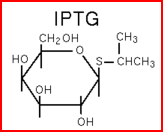
We "tell" our cells to start making the "dice"--T7 polymease by applying a pulse of IPTG. IPTG can activate the araC/pBAD promoter which leads to transcription of T7 polymerase.
"Throwing the dice"
The core part of the randomizer consists of a pair of overlapping T7 promoters having similar binding affinities. The T7 polymerase binds randomly onto either the left or the right promoter to give an either 0 or 1 signal (reprenting by giving RFP or GFP).The binding is mutually exclusive, for if one binds to the promoter, it will block the binding of the other one as the two T7 promoters are overlapping to each other.
Reciprocal inhibiton
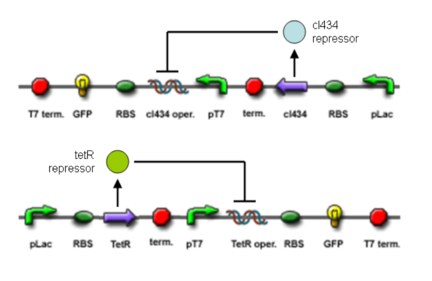
Then there are TetR and C1434 repressor repressor genes on both sides respectively. A repressor protein can be produced to interrupt transcription on the other side of the circuit.
For example, say, the T7 polymerase binds onto the promoter on the left side. The TetR repressor on the left, which was coded by TetR repressor gene, will bind to TetR operator on the right and repress transcription of right side of the promoter. Thus, the intial random event (binding of polymease) can be captured and amplified in a postive feedback circuit.

Final outcome
- Continous production of GFP if the polymease binds to the left of overlapped T7 promoter
- Continous production of RFP if the polymease binds to the right of overlapped T7 promoter
Construction details
Testing
Strain and vector used
- Strain: E. coli BBa_V1001 DH5a, with genotype
F-φ80dlacZΔM15 Δ(lacZYA-argF)U169 deoR recA1 endA1 hsdR17(rk- mk+ phoA supE44 λ- thi-1 gyrA96 relA1)
- Vector: pUC18+ λ-InCh2
Integration system
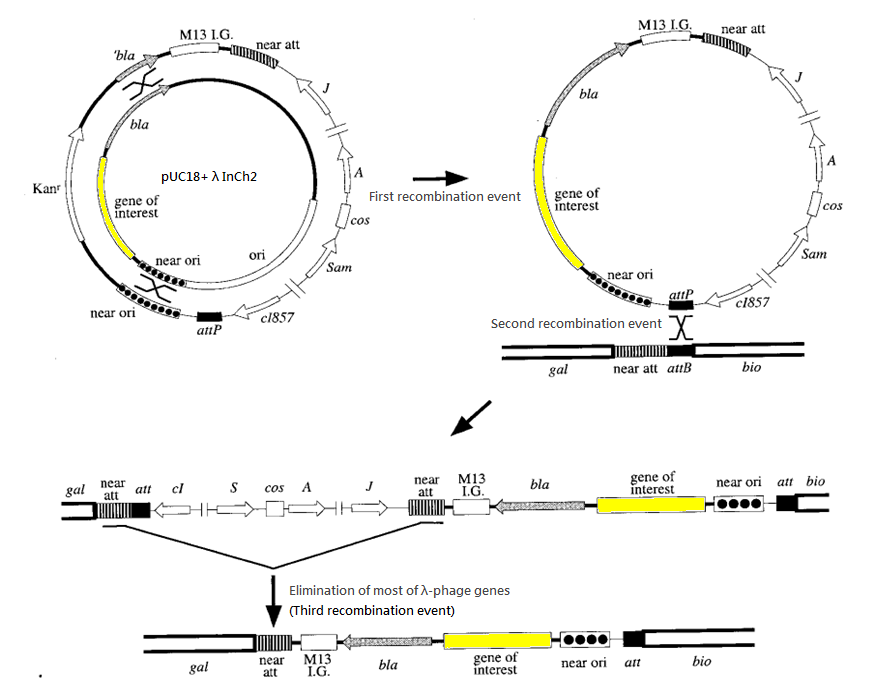
To ensure the randomness of the system we make, we should make sure there is only one copy of the circuit. Therefore, we are trying to incoporate the circuit into the chromosome.
We have chosen the λInCh system as the vehicle for intergration.

The success rate for recombination is about 1 in 1000 cells. Ampicillin is used to screen for the second recombination event and temperatute of 42 degree Celsius is used to screen for the third recombination event. (Such temperature deactivates the cl857 repressor and hence activates the harmful gene of λ-phage introduced in second recombination event, killing the host cells.)
The advantages of this approach include:
- No risk of >1 copy of target gene in our machine, so as to give a sharp output instead of "blurred" output caused by multiple copies
- Stable integration of a single copy of the construct DNA fragment
- Most ordinary E. coli strains and a variety of pBR322-derived Amp-resistant plasmids can be used
- λ-phage as the only specialized vector required
- Source:
Boyd D., Weiss D.S., Chen J.C., Beckwith J., Towards single-copy gene expression systems making gene cloning physiologically relevant: Lambda InCh, a simple Escherichia coli plasmid- chromosome shuttle system (2000) Journal of Bacteriology, 182 (3), pp. 842-847.
The Initial Proposal
The first draft of project description
The HKUSTers’ project is composed of three components; (1) a Randomizer with one of the two possible random outputs at a single cell level, (2) a Memorizer that specifically records the last input and compares it with the current input to give out an XOR calculation, while the input before the last is erased, and (3) a Spatial Oscillator that facilitates autonomous back and forth migration of cells responding to two opposing chemical gradients.
Our project objective is to construct a biological slot machine by coupling the Randomizer with the Memorizer. When two consecutive random signals are produced by the Randomizer, a Memorizer can evaluate whether the two signals are the same so as to display a Jackpot output. Coupling of the Randomizer and a Spatial Oscillator can generate a dynamic pattern, such as dots and stripes, whereas modifications of the Spatial Oscillator can be introduced to produce an automatic and more complex oscillation pattern. With these three building blocks integrated in specific manner, different dynamic patterns can be generated to recreate stripes and pigmented profiles as found in many biological systems. The components also constitute the foundation units subjected to scale up assembly of more complex operations.
 "
"


