Team:Bologna/Modeling
From 2008.igem.org
| Line 27: | Line 27: | ||
== The genetic Flip-Flop == | == The genetic Flip-Flop == | ||
| - | |||
<br> | <br> | ||
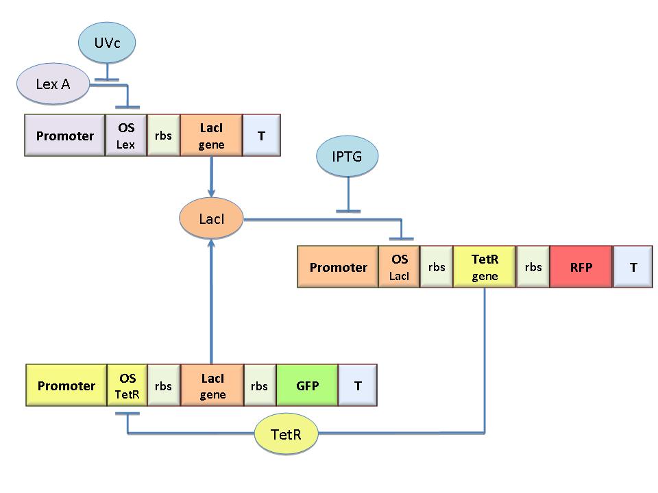
The molecular circuit in Figure 1 works as a Flip-Flop (SR Latch), which can switch between two different states according to the external stimuli (UVc and IPTG). | The molecular circuit in Figure 1 works as a Flip-Flop (SR Latch), which can switch between two different states according to the external stimuli (UVc and IPTG). | ||
| Line 33: | Line 32: | ||
[[Image:Circuito2.jpg|300px|thumb|right|Figure 1: Scheme of the genetic Flip-Flop]] | [[Image:Circuito2.jpg|300px|thumb|right|Figure 1: Scheme of the genetic Flip-Flop]] | ||
<br> | <br> | ||
| + | |||
LacI-ON represents the stable state in which LacI gene is active and LacI protein represses the TetR gene expression, with a positive feedback.<br> Therefore, the LacI-ON state coincides with the TetR-OFF condition. On the contrary, the TetR-ON represents the state with the TetR gene active and the LacI gene silenced (LacI-OFF). Owing to the coexistence of two stable states (bistability), this circuit is capable of serving as a binary of memory. We denominated it Flip-Flop since it works as a SR Latch: LacI state is the output and TetR state is the output. Uvc is the set signal and IPTG is the reset signal. Indeed, IPTG stimulation inhibits LacI repressor, thus can cause the transition from the LacI-ON state to the TetR-ON, whereas UVc radiation inactiving LexA repressor through the SOS response (Friedberg et al., 1995) can cause the opposite transition from LacI-ON to TetR-ON. | LacI-ON represents the stable state in which LacI gene is active and LacI protein represses the TetR gene expression, with a positive feedback.<br> Therefore, the LacI-ON state coincides with the TetR-OFF condition. On the contrary, the TetR-ON represents the state with the TetR gene active and the LacI gene silenced (LacI-OFF). Owing to the coexistence of two stable states (bistability), this circuit is capable of serving as a binary of memory. We denominated it Flip-Flop since it works as a SR Latch: LacI state is the output and TetR state is the output. Uvc is the set signal and IPTG is the reset signal. Indeed, IPTG stimulation inhibits LacI repressor, thus can cause the transition from the LacI-ON state to the TetR-ON, whereas UVc radiation inactiving LexA repressor through the SOS response (Friedberg et al., 1995) can cause the opposite transition from LacI-ON to TetR-ON. | ||
== Mathematical model == | == Mathematical model == | ||
| + | <br> | ||
=== Model equations === | === Model equations === | ||
| - | + | <br> | |
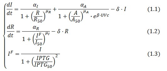
The Flip-Flop circuit in Figure 1 can be modeled by the following equations: | The Flip-Flop circuit in Figure 1 can be modeled by the following equations: | ||
[[Image:Equazioni.jpg|center]] | [[Image:Equazioni.jpg|center]] | ||
| Line 49: | Line 50: | ||
=== Adimensional equations === | === Adimensional equations === | ||
| - | + | <br> | |
The equations (1.1) and (1.2) can be written dimensionless: | The equations (1.1) and (1.2) can be written dimensionless: | ||
| Line 59: | Line 60: | ||
[[Image:f005new.jpg|center]] | [[Image:f005new.jpg|center]] | ||
| - | + | <br> | |
[https://2008.igem.org/Team:Bologna/Modeling ''Up''] | [https://2008.igem.org/Team:Bologna/Modeling ''Up''] | ||
== Adimensional equations == | == Adimensional equations == | ||
| - | |||
<br> | <br> | ||
| Line 73: | Line 73: | ||
[[Image:equa2new.jpg|center]] | [[Image:equa2new.jpg|center]] | ||
| - | + | <br> | |
[https://2008.igem.org/Team:Bologna/Modeling ''Up''] | [https://2008.igem.org/Team:Bologna/Modeling ''Up''] | ||
== Equibrium conditions == | == Equibrium conditions == | ||
| - | + | <br> | |
In the absence of stimuli, the adimensional concentrations of LacI ( ) and TetR ( ) at equilibrium are related by the equations: | In the absence of stimuli, the adimensional concentrations of LacI ( ) and TetR ( ) at equilibrium are related by the equations: | ||
[[Image:equa3new.jpg|center]] | [[Image:equa3new.jpg|center]] | ||
| - | + | <br> | |
To obtain these relations the UVc-dependent term in equation (1.4) was ignored ( ). This is justified by the high binding constant of LexA for its operator, and the consequent negligible contribution to the LacI synthesis. | To obtain these relations the UVc-dependent term in equation (1.4) was ignored ( ). This is justified by the high binding constant of LexA for its operator, and the consequent negligible contribution to the LacI synthesis. | ||
Equations (1.6) and (1.7) can have one or three solutions that represent the equilibrium conditions of the circuit. The solutions, i.e. the equilibrium conditions, can be graphically identified as the intersections between r and i nullclines (see Figure 2). The case of multiple equilibrium conditions (bistability case) is shown in Figure 2 panel b). TetR-ON and LacI-ON are stable equilibriums separated by the unstable one (saddle point). Due to the bistability the circuit can operate as a binary memory. | Equations (1.6) and (1.7) can have one or three solutions that represent the equilibrium conditions of the circuit. The solutions, i.e. the equilibrium conditions, can be graphically identified as the intersections between r and i nullclines (see Figure 2). The case of multiple equilibrium conditions (bistability case) is shown in Figure 2 panel b). TetR-ON and LacI-ON are stable equilibriums separated by the unstable one (saddle point). Due to the bistability the circuit can operate as a binary memory. | ||
| Line 87: | Line 87: | ||
[[Image:equicondition.jpg|center]] | [[Image:equicondition.jpg|center]] | ||
| - | + | <br> | |
== Bifurcation analysis == | == Bifurcation analysis == | ||
| + | <br> | ||
Assuming that LacI-ON exists the corresponding equilibrium value of is higher than 1 (see Figure 2), then it can be assumed that and the equation (1.7) simplies to: | Assuming that LacI-ON exists the corresponding equilibrium value of is higher than 1 (see Figure 2), then it can be assumed that and the equation (1.7) simplies to: | ||
| - | |||
[[Image:equa1_8.jpg|center]] | [[Image:equa1_8.jpg|center]] | ||
| Line 102: | Line 102: | ||
[[Image:equa1_10.jpg|center]] | [[Image:equa1_10.jpg|center]] | ||
| + | <br> | ||
[[Image:.jpg|center]] | [[Image:.jpg|center]] | ||
| + | <br> | ||
To be real the solutions of equation (1.10) it is necessary that (see Figure 3). Under this condition the existence of the LacI-ON state is assured. When the system undergoes a saddle-node bifurcation (LacI-ON and saddle point go in collision) and the two equilibrium points vanish. | To be real the solutions of equation (1.10) it is necessary that (see Figure 3). Under this condition the existence of the LacI-ON state is assured. When the system undergoes a saddle-node bifurcation (LacI-ON and saddle point go in collision) and the two equilibrium points vanish. | ||
| - | + | <br> | |
[[Image:SaddleNodebifurcation.jpg|center]] | [[Image:SaddleNodebifurcation.jpg|center]] | ||
| + | <br> | ||
An analogous result can be obtained for the existence of the TetR-ON state. Thus, a sufficient condition for bistability is: | An analogous result can be obtained for the existence of the TetR-ON state. Thus, a sufficient condition for bistability is: | ||
[[Image:Equa1_11.jpg|center]] | [[Image:Equa1_11.jpg|center]] | ||
| - | + | <br> | |
[[Image:Equa1_12.jpg|center]] | [[Image:Equa1_12.jpg|center]] | ||
| - | + | <br> | |
Figure 4 shows the log-log plot of (1.11) and (1.12) | Figure 4 shows the log-log plot of (1.11) and (1.12) | ||
| - | + | <br> | |
[[Image:Rangeofbistability.jpg|center]] | [[Image:Rangeofbistability.jpg|center]] | ||
| - | + | <br> | |
[https://2008.igem.org/Team:Bologna/Modeling ''Up''] | [https://2008.igem.org/Team:Bologna/Modeling ''Up''] | ||
== Procedure for -index identification == | == Procedure for -index identification == | ||
| + | <br> | ||
The procedure will be described for LacI, analogous procedure can be applied to the TetR case. The value of -index can be identified comparing the experimental responses of the open loop and closed loop circuits: | The procedure will be described for LacI, analogous procedure can be applied to the TetR case. The value of -index can be identified comparing the experimental responses of the open loop and closed loop circuits: | ||
| - | + | <br> | |
[[Image:Molecularcircuits.jpg|center]] | [[Image:Molecularcircuits.jpg|center]] | ||
| - | + | <br> | |
The LacI concentration in the open loop circuit is given by: | The LacI concentration in the open loop circuit is given by: | ||
| - | + | <br> | |
[[Image:Equa1_13.jpg]] | [[Image:Equa1_13.jpg]] | ||
| - | + | <br> | |
Thus the equilibrium condition is: | Thus the equilibrium condition is: | ||
| + | <br> | ||
[[Image:Equa1_14.jpg]] | [[Image:Equa1_14.jpg]] | ||
| + | <br> | ||
The time derivative of LacI concentration in the close loop circuit follows: | The time derivative of LacI concentration in the close loop circuit follows: | ||
| + | <br> | ||
[[Image:Equa1_15.jpg]] | [[Image:Equa1_15.jpg]] | ||
| - | + | <br> | |
Which gives the equilibrium condition: | Which gives the equilibrium condition: | ||
| + | <br> | ||
[[Image:Equa1_16.jpg]] | [[Image:Equa1_16.jpg]] | ||
| + | <br> | ||
That can be rewritten | That can be rewritten | ||
| + | <br> | ||
[[Image:Equa1_17.jpg]] | [[Image:Equa1_17.jpg]] | ||
| - | + | <br> | |
The affinity coefficient can consequently be derived from this expression | The affinity coefficient can consequently be derived from this expression | ||
| + | <br> | ||
[[Image:Equa1_18.jpg]] | [[Image:Equa1_18.jpg]] | ||
| - | + | <br> | |
Inserting the (1.14) and (1.18) in the -index definition one obtain: | Inserting the (1.14) and (1.18) in the -index definition one obtain: | ||
| + | <br> | ||
[[Image:Equa1_19.jpg]] | [[Image:Equa1_19.jpg]] | ||
| - | + | <br> | |
We assume that GFP is proportion to , then | We assume that GFP is proportion to , then | ||
| + | <br> | ||
[[Image:Equa1_20.jpg]] | [[Image:Equa1_20.jpg]] | ||
| + | <br> | ||
We introduce the ratio between the fluorescence in open loop and in closed loop: | We introduce the ratio between the fluorescence in open loop and in closed loop: | ||
| + | <br> | ||
[[Image:Equa1_21.jpg]] | [[Image:Equa1_21.jpg]] | ||
| - | After measuring the ratio it is possible to calculate by the curve in Figure 6 and then it is possible to establish by Figure 4 the range that guarantees bistability. In the presence of an experimentally characterized library of regulated promoter, the procedure can be adopted to design genetic Flip-Flop with desired behaviors. | + | <br> |
| + | After measuring the ratio it is possible to calculate by the curve in Figure 6 and then it is possible to establish by Figure 4 the range that guarantees bistability. In the presence of an experimentally characterized library of regulated promoter, the procedure can be adopted to design genetic Flip-Flop with desired behaviors.<br> | ||
[[Image:indexforlaci.jpg]] | [[Image:indexforlaci.jpg]] | ||
Revision as of 14:45, 27 October 2008
| HOME | TEAM | PROJECT | MODELING | WET-LAB | SOFTWARE | SUBMITTED PARTS | BIOSAFETY AND PROTOCOLS |
|---|
Contents |
Model-based analysis of the genetic Flip-Flop
The genetic Flip-Flop
The molecular circuit in Figure 1 works as a Flip-Flop (SR Latch), which can switch between two different states according to the external stimuli (UVc and IPTG).
LacI-ON represents the stable state in which LacI gene is active and LacI protein represses the TetR gene expression, with a positive feedback.
Therefore, the LacI-ON state coincides with the TetR-OFF condition. On the contrary, the TetR-ON represents the state with the TetR gene active and the LacI gene silenced (LacI-OFF). Owing to the coexistence of two stable states (bistability), this circuit is capable of serving as a binary of memory. We denominated it Flip-Flop since it works as a SR Latch: LacI state is the output and TetR state is the output. Uvc is the set signal and IPTG is the reset signal. Indeed, IPTG stimulation inhibits LacI repressor, thus can cause the transition from the LacI-ON state to the TetR-ON, whereas UVc radiation inactiving LexA repressor through the SOS response (Friedberg et al., 1995) can cause the opposite transition from LacI-ON to TetR-ON.
Mathematical model
Model equations
The Flip-Flop circuit in Figure 1 can be modeled by the following equations:
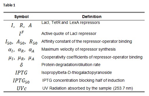
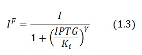
Symbol definition is listed in Table 1.
A common motif in repressor proteins is the presence of a dimeric nucleotide-binding site with dimeric structure. In accordance to this general structure the cooperativity coefficients ( ) were assumed equal to 2. The maximum velocity of repressor synthesis ( accounts for the strength of the unregulated promoter and RBS. The value of the affinity constant for the binding of repressor to the promoter strictly depends on the sequence of operator site (OS block).
Adimensional equations
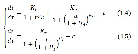
The equations (1.1) and (1.2) can be written dimensionless:
Adimensional equations
The equations (1.1) and (1.2) were modified to an adimensional form:
Equibrium conditions
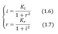
In the absence of stimuli, the adimensional concentrations of LacI ( ) and TetR ( ) at equilibrium are related by the equations:
To obtain these relations the UVc-dependent term in equation (1.4) was ignored ( ). This is justified by the high binding constant of LexA for its operator, and the consequent negligible contribution to the LacI synthesis.
Equations (1.6) and (1.7) can have one or three solutions that represent the equilibrium conditions of the circuit. The solutions, i.e. the equilibrium conditions, can be graphically identified as the intersections between r and i nullclines (see Figure 2). The case of multiple equilibrium conditions (bistability case) is shown in Figure 2 panel b). TetR-ON and LacI-ON are stable equilibriums separated by the unstable one (saddle point). Due to the bistability the circuit can operate as a binary memory.
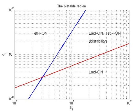
The existence of a bistability condition depends on the value of Kr and Ki parameters. If Kr decrease (see Figure 2 pannel (a)) a saddle-node bifurcation can occur, TetR-ON equilibrium vanishes and remain only the stable equilibrium LacI-ON. The contrary occurs when Ki is decreased (Figure 2 pannel (c)). Thus bistability is guarantied only for a limited range of and values.
Bifurcation analysis
Assuming that LacI-ON exists the corresponding equilibrium value of is higher than 1 (see Figure 2), then it can be assumed that and the equation (1.7) simplies to:
Substituting this expression in equation (1.6) one obtain:
Then:
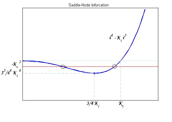
To be real the solutions of equation (1.10) it is necessary that (see Figure 3). Under this condition the existence of the LacI-ON state is assured. When the system undergoes a saddle-node bifurcation (LacI-ON and saddle point go in collision) and the two equilibrium points vanish.
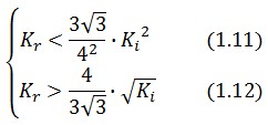
An analogous result can be obtained for the existence of the TetR-ON state. Thus, a sufficient condition for bistability is:
Figure 4 shows the log-log plot of (1.11) and (1.12)
Procedure for -index identification
The procedure will be described for LacI, analogous procedure can be applied to the TetR case. The value of -index can be identified comparing the experimental responses of the open loop and closed loop circuits:
The LacI concentration in the open loop circuit is given by:

Thus the equilibrium condition is:

The time derivative of LacI concentration in the close loop circuit follows:

Which gives the equilibrium condition:

That can be rewritten

The affinity coefficient can consequently be derived from this expression

Inserting the (1.14) and (1.18) in the -index definition one obtain:

We assume that GFP is proportion to , then

We introduce the ratio between the fluorescence in open loop and in closed loop:

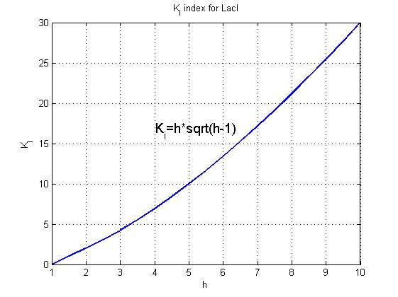
After measuring the ratio it is possible to calculate by the curve in Figure 6 and then it is possible to establish by Figure 4 the range that guarantees bistability. In the presence of an experimentally characterized library of regulated promoter, the procedure can be adopted to design genetic Flip-Flop with desired behaviors.
 "
"


