Team:UNIPV-Pavia/Project
From 2008.igem.org
| Line 36: | Line 36: | ||
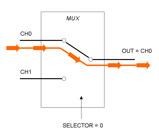
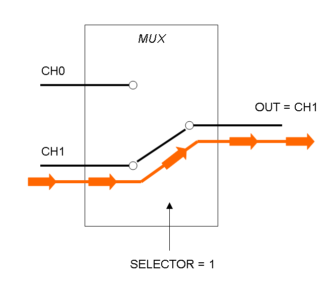
|[[Image:pv_mux_dataflux1.png|thumb|300px|center|Data flux in Multiplexer - SELECTOR=1]] | |[[Image:pv_mux_dataflux1.png|thumb|300px|center|Data flux in Multiplexer - SELECTOR=1]] | ||
|- | |- | ||
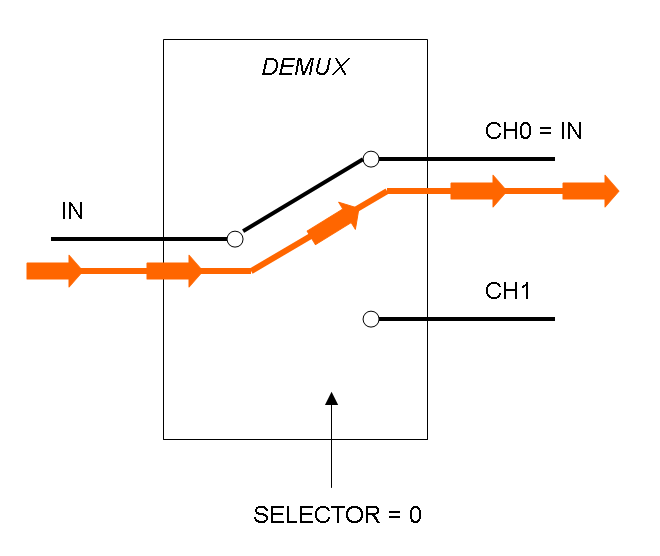
| - | |[[Image:pv_demux_dataflux0.png|thumb|300px| | + | |[[Image:pv_demux_dataflux0.png|thumb|300px|left|Data flux in Demultiplexer - SELECTOR=0]] |
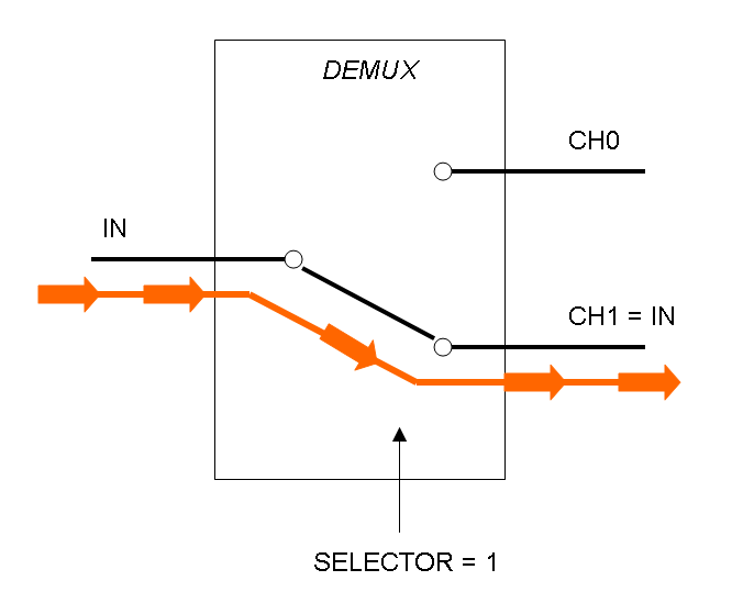
|[[Image:pv_demux_dataflux1.png|thumb|300px|center|Data flux in Demultiplexer - SELECTOR=1]] | |[[Image:pv_demux_dataflux1.png|thumb|300px|center|Data flux in Demultiplexer - SELECTOR=1]] | ||
|} | |} | ||
Revision as of 14:37, 8 June 2008
Contents |
Overall project
We are trying to mimic Multiplexer (Mux) and Demultiplexer (Demux) logic functions in E. coli.
In the following paragraphs project details will be described from both digital electronic and genetic points of view.
Electronic Implementation
What kind of components are Mux and Demux?
Mux is a component which conveys one of the two input channels values into a single output channel. The choice of the input channel is made by a selector.
Demux is a component which conveys the only input channel value into one of the two output channels. The choice of the output channel is made by a selector.
What kind of signals do we process?
In this project we consider Boolean logic signals, thus every input/output value can assume only the values of 0 and 1. A function that processes Boolean values is called logic function.
Mux and Demux can be considered by now as black boxes which implement a logic function that can process input signals to output signals. In the following documentation we will see what is inside this black boxes.
How can we formalize Mux and Demux logic behavior?
Logic functions can be formalized writing a truth table; a truth table is a mathematical table in which every row represents a combination of input values and its respective output values. The table has to be filled with every input combination.
Here you can see Mux and Demux truth tables:
Building a logic circuit from a truth table
Our goal in this section is to project two logic gates networks which behave like Mux and Demux truth tables. A very useful tool to transform a truth table into a logic network is Karnaugh map.
It is possible to read about Karnaugh maps at: [http://en.wikipedia.org/wiki/Karnaugh_map]
Following Karnaugh maps method, we can write these two maps and these two logic networks for Mux and Demux:
 "
"


