Team:Imperial College/Genetic Circuit

From 2008.igem.org

(Difference between revisions)
(Undo revision 59569 by Erikacule (Talk))
Line 24: Line 24:
<br>
<br>
Note from the parameter scan graphs:<br>
-
*In the case where <math>k_1 {{Equals}} 0</math>, no GFP is sythesised.
+
*In the case where k1 {{Equals}} 0, no GFP is sythesised.
-
*In the case where <math>d_1 {{Equals}} 0</math>, the concentration of protein does not reach a steady state.
+
*In the case where d1 {{Equals}} 0, the concentration of protein does not reach a steady state.
|[[Image:Phase 1.PNG|thumb|300px|Constitutive expression of antibiotic resistance (AB) and GFP. GFP brick is part E0040, GFPmut3b. Terminator is part B0015, the double-stop.]]
|[[Image:Phase 1.PNG|thumb|300px|Constitutive expression of antibiotic resistance (AB) and GFP. GFP brick is part E0040, GFPmut3b. Terminator is part B0015, the double-stop.]]

Revision as of 14:56, 21 October 2008

Modelling the Genetic Circuit

An accurate mathematical description of the genetic circuit is essential for projects involving synthetic biology. Such descriptions are an integral component of part submission to the Registry, as exemplified by the canonical characterisation of part F2620 #1. The ability to capture part behaviour as a mathematical relationship between input and output is useful for future re-use of the part and modification of integration into novel genetic circuits.


Modelling Constitutive Gene Expression

A simple synthesis-degradation model is assumed for the modelling of the expression of a protein under the control of a constitutive promoter, with the same model assumed for all four promoter-RBS constructs. The synthesis-degradation model assumes a steady state level of mRNA.

Eq1.png

In this case, [protein] represents the concentration of GFP, k1 represents the rate of sythesis and d1 represents the degradation rate. We can easily simulate this synthesis-degradation model using matlab:
ODE
Simulation File

We can also solve this ODE analytically. Consider the steady-state behaviour of <math>[protein]</math>.

Eq2.png

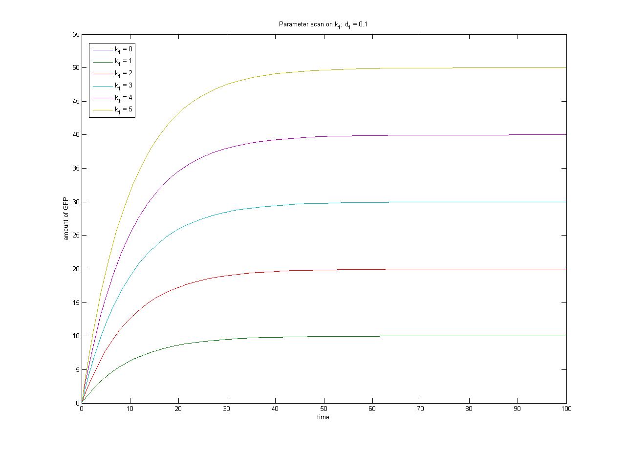
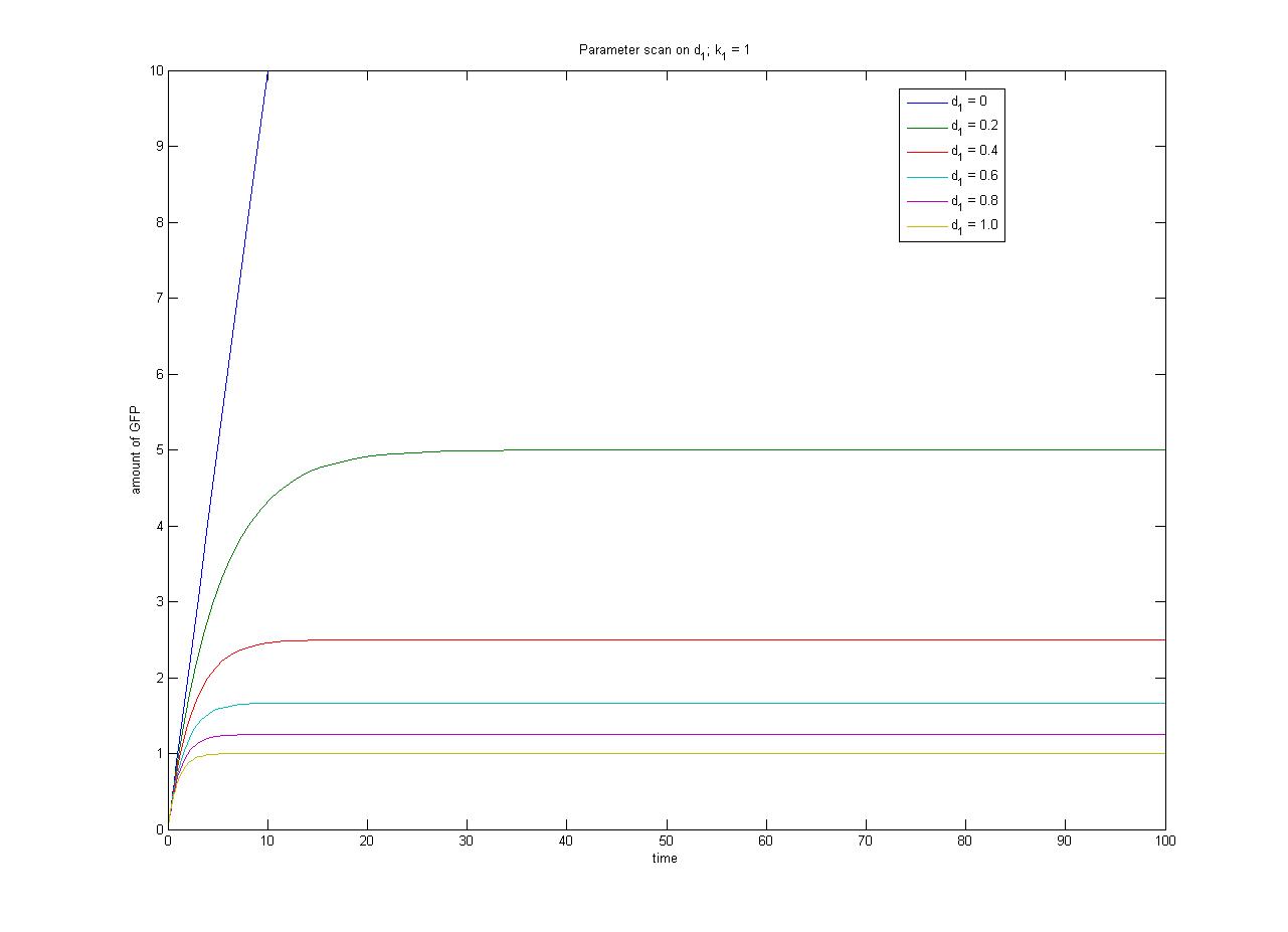
This relationship can be seen in the parameter scan graphs on the right.

From the wetlab experiments it is likely that we will obtain steady-state data for each of the four promoter-RBS constructs. If we assume the same rate of degradation of GFP in each case, we can have some measure of the relative rate of transcription through each promoter which will help us with the selection of the most appropriate promoter to use for Phase 2. In order to obtain an absolute measure of transcription (as opposed to a relative measure of transcriptional strength) we require constitutive expression in terms of molecules per cell (as opposed to fluorescence in arbitrary units).
Note from the parameter scan graphs:

  • In the case where k1 = 0, no GFP is sythesised.
  • In the case where d1 = 0, the concentration of protein does not reach a steady state.
Constitutive expression of antibiotic resistance (AB) and GFP. GFP brick is part E0040, GFPmut3b. Terminator is part B0015, the double-stop.

Modelling Inducible Gene Expression
Phase 2-linduced.PNG

The repressor is constitutively expressed. Hence we can assume the constitutive expression model from the previous characterisation step.

Eq3.png

When the inducer is added it binds reversibly to the repressor.

Eq4.png

Repressor only binds to the promoter when it is in its unbound form, hence transcription will be a function of free repressor concentration.

Eq5.png

And overall protein expression can be described as

Eq6.png

The ODEs and simulation may be found in the Appendices section of the Dry Lab hub.

<biblio>

  1. 1 pmid=18612302

</biblio>