Team:EPF-Lausanne/Modeling
From 2008.igem.org
(→Simulation) |
(→Simulation) |
||
| Line 38: | Line 38: | ||
====Simulation==== | ====Simulation==== | ||
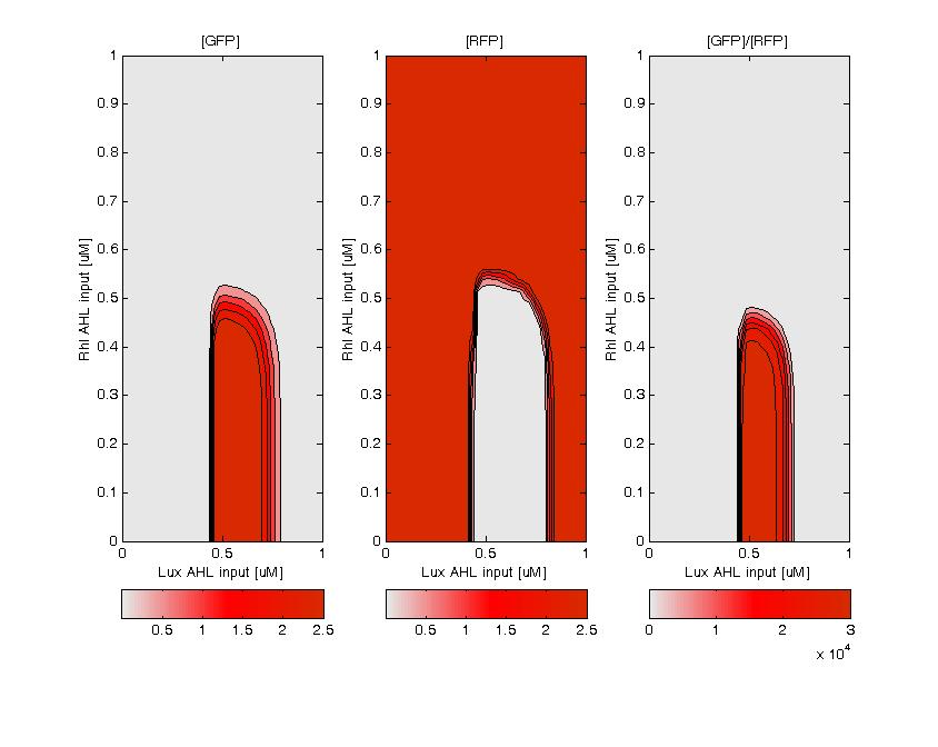
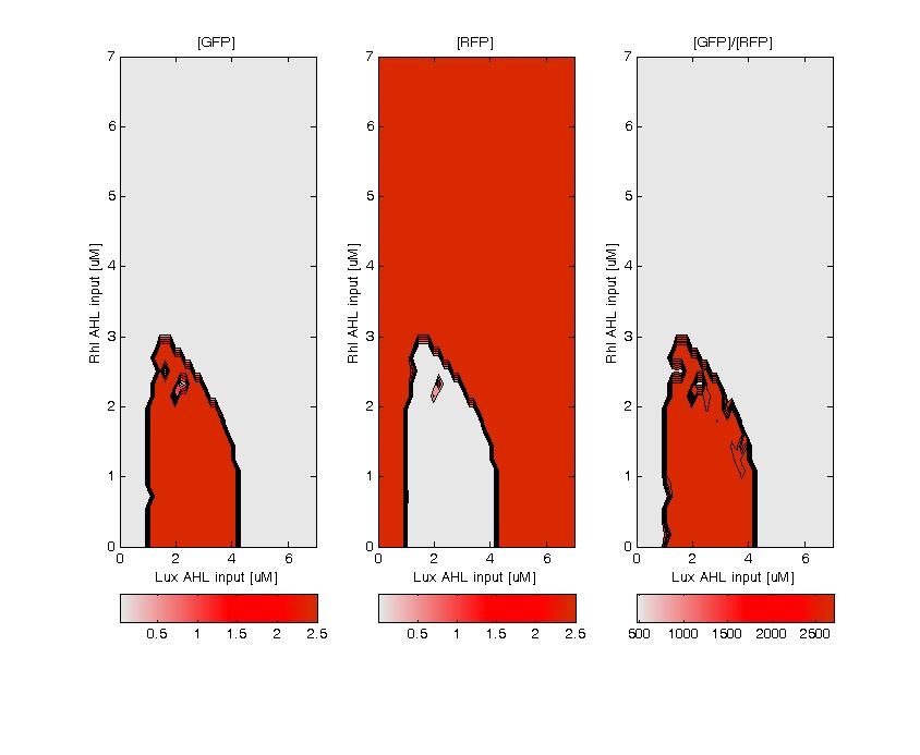
| - | + | GFP (left) and RFP (middle) expression for concentration of AHL (Lux or Rhl) pulses. On the right, figure shows the ratio of GFP/RFP. | |
| - | [Image:bistabl_sim.jpg]] | + | [[Image:bistabl_sim.jpg]] |
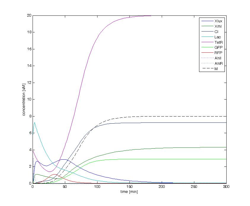
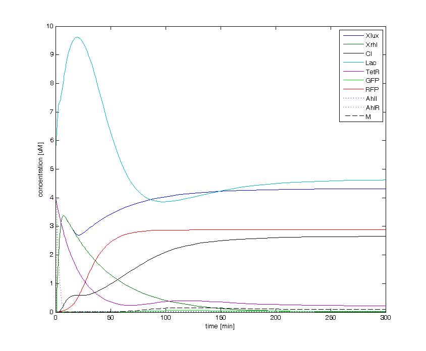
The following figures show the dynamics of the different states involved in the system for different AHL pulses. On the left, the system is locked into the green state after a pulse of 1.6 uM of Lux AHL and 3 uM of Rhl AHL. On the right, the system is locked into the red state after a pulse of 4 uM of Lux AHL and 4 uM of Rhl AHL. The model nicely shows the dominance of either TetR (purple line) or LacI (light blue line) for the green, respectively red state. It also shows the importance of the twos negative feedback made by the M represssor (dashed line) and CI (black line) to maintain the system in the green state. | The following figures show the dynamics of the different states involved in the system for different AHL pulses. On the left, the system is locked into the green state after a pulse of 1.6 uM of Lux AHL and 3 uM of Rhl AHL. On the right, the system is locked into the red state after a pulse of 4 uM of Lux AHL and 4 uM of Rhl AHL. The model nicely shows the dominance of either TetR (purple line) or LacI (light blue line) for the green, respectively red state. It also shows the importance of the twos negative feedback made by the M represssor (dashed line) and CI (black line) to maintain the system in the green state. | ||
Revision as of 17:00, 29 October 2008
| Home | The Team | The Project | Parts | 2-step PCR | Microfluidics | Modeling | Notebook |
|---|
Contents |
Double input model
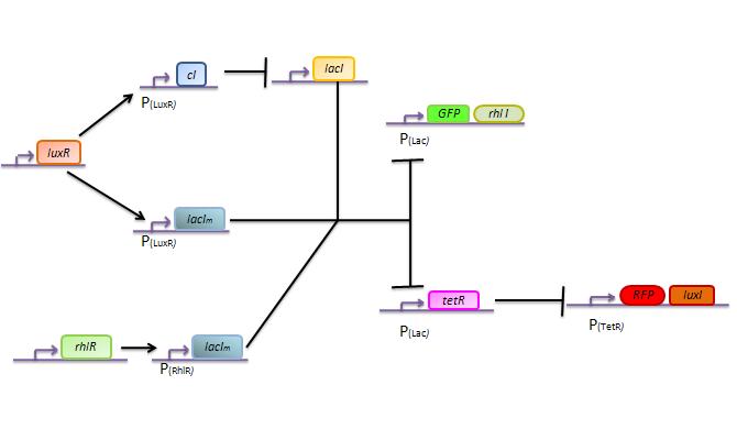
Here we describe a semi-quantitative model of the Lux band-pass detector and the Rhl high-pass detector. The model describes each proteins and sending molecules involved in the system.
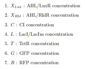
States
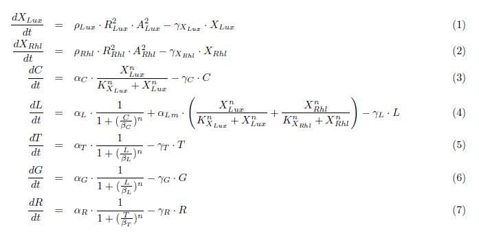
ODEs
Parameters
Simulation
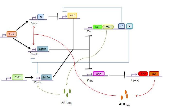
Bistable switch model
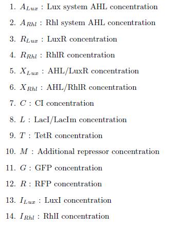
States
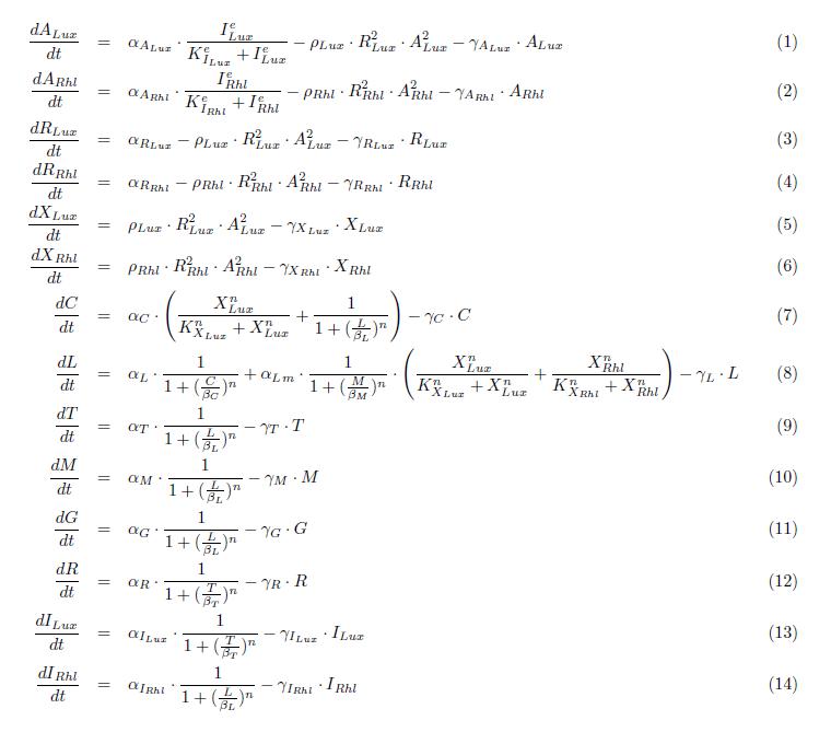
ODEs
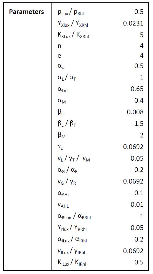
Parameters
Simulation
GFP (left) and RFP (middle) expression for concentration of AHL (Lux or Rhl) pulses. On the right, figure shows the ratio of GFP/RFP.
The following figures show the dynamics of the different states involved in the system for different AHL pulses. On the left, the system is locked into the green state after a pulse of 1.6 uM of Lux AHL and 3 uM of Rhl AHL. On the right, the system is locked into the red state after a pulse of 4 uM of Lux AHL and 4 uM of Rhl AHL. The model nicely shows the dominance of either TetR (purple line) or LacI (light blue line) for the green, respectively red state. It also shows the importance of the twos negative feedback made by the M represssor (dashed line) and CI (black line) to maintain the system in the green state.
 "
"
