Team:UNIPV-Pavia/Project
From 2008.igem.org
Contents |
Overall project
We are trying to mimic Multiplexer (Mux) and Demultiplexer (Demux) logic functions in E. coli.
In the following paragraphs project details will be described from both digital electronic and genetic points of view.
Electronic Implementation
What kind of components are Mux and Demux?
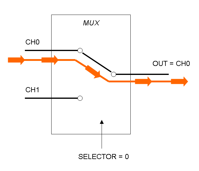
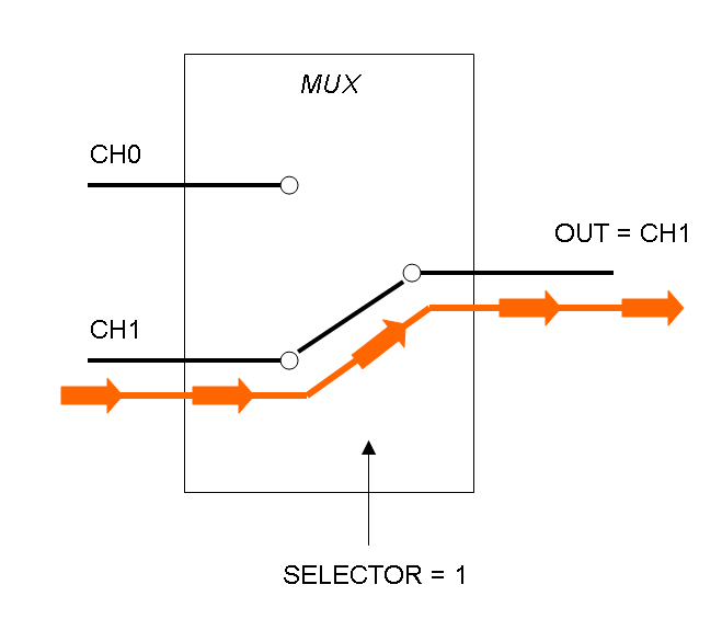
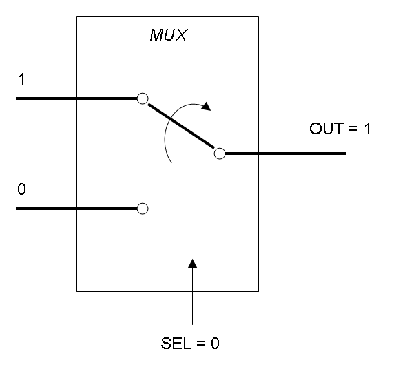
Mux is a component which conveys one of the two input channels values into a single output channel. The choice of the input channel is made by a selector.
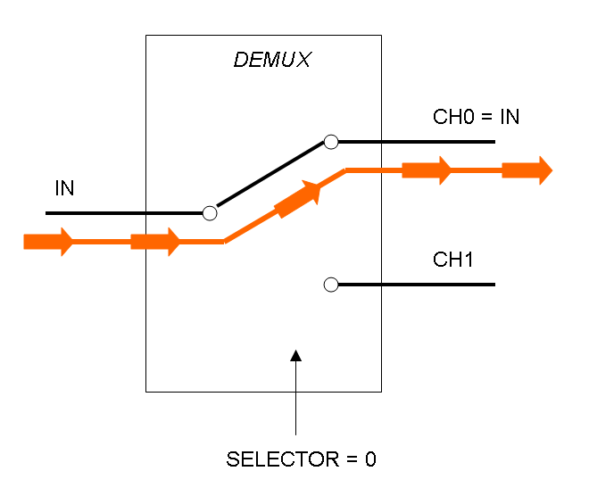
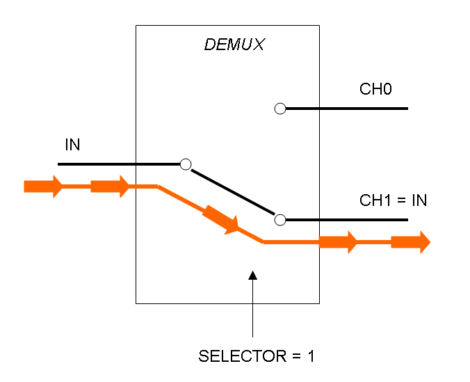
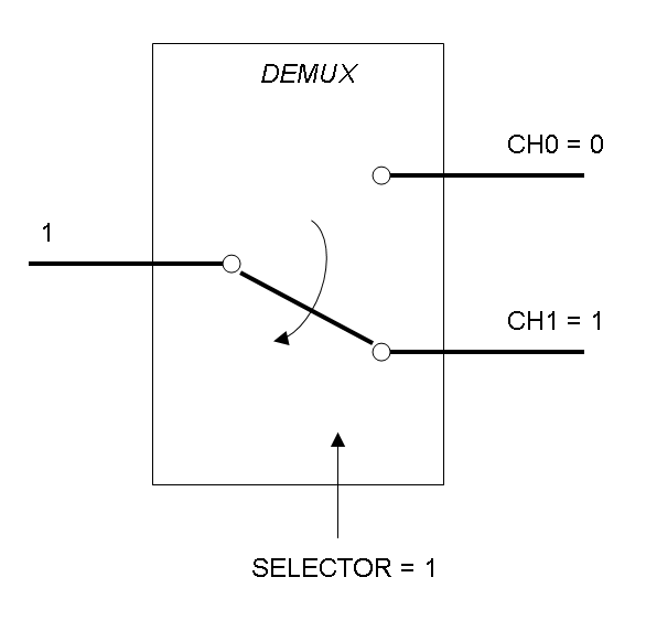
Demux is a component which conveys the only input channel value into one of the two output channels. The choice of the output channel is made by a selector.
The following pictures show data flow in Mux and Demux:
What kind of signals do we process?
In this project we consider Boolean logic signals, thus every input/output value can assume only the values 0 and 1. A function that processes Boolean values is called logic function.
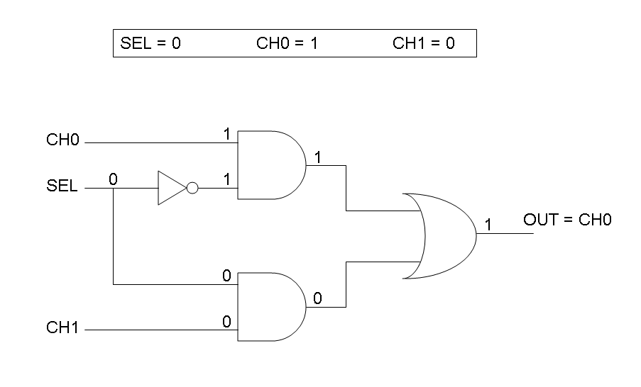
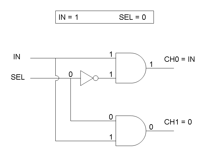
Mux and Demux can be considered by now as black boxes which implement a logic function that can process input signals to output signals. Here you can see examples of Boolean data flow in Mux and Demux:
In the following documentation we will see what is inside these black boxes.
How can we formalize Mux and Demux logic behavior?
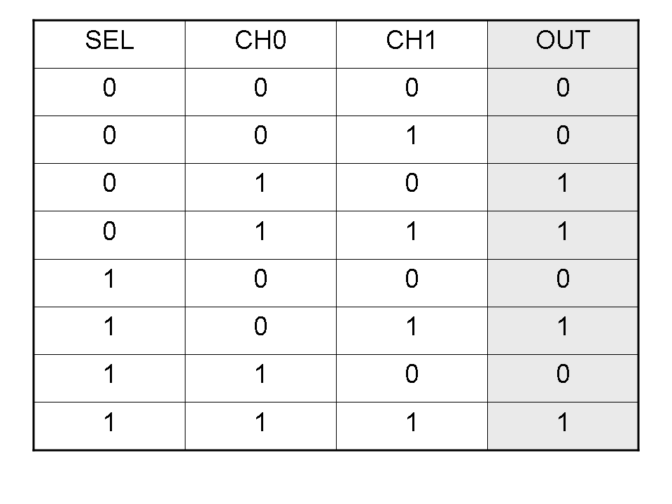
Logic functions can be formalized writing a truth table; a truth table is a mathematical table in which every row represents a combination of input values and its respective output values. The table has to be filled with every input combination.
Here you can see Mux and Demux truth tables (output columns are gray):
Building a logic circuit from a truth table
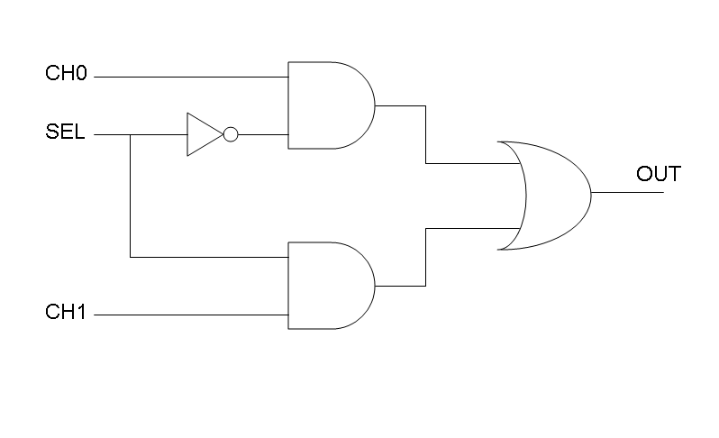
Our goal in this section is to project two logic gates networks which behave like Mux and Demux truth tables. A very useful tool to transform a truth table into a logic network is Karnaugh map.
It is possible to read about Karnaugh maps at: [http://en.wikipedia.org/wiki/Karnaugh_map]
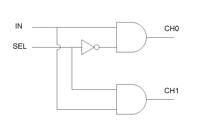
Following Karnaugh maps method, we can write these two logic networks for Mux and Demux:
Genetic Implementation
Our goal is to mimic Mux and Demux logic networks in a biological device, such as E. coli. To perform this, we use protein/DNA and protein/protein interactions to build up biological logic gates.
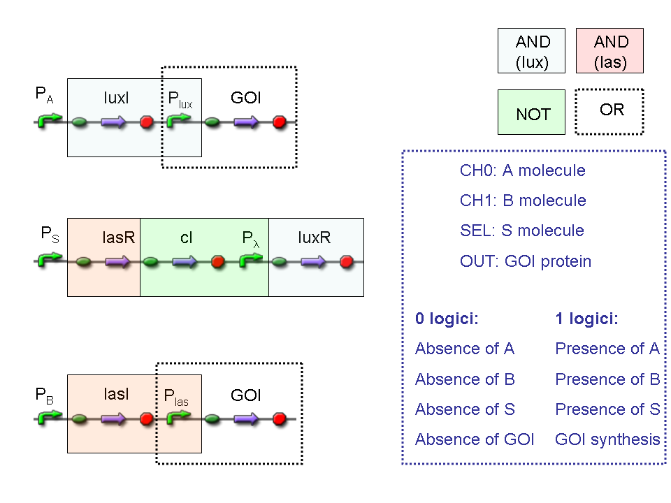
Mux and Demux logic circuits are composed by three fundamental logic gates, AND, OR, NOT: in the next paragraphs genetic implementation of these logic gates will be provided.
AND
To mimic an AND gate, we need a biological function, such as a promoter activation, which is directly turned on by the interaction between two upstream genes. In our synthetic devices, we use the luxR/luxI system: luxR can activate Plux promoter only upon 3-oxo-hexanoyl-homoserine lactone (HSL) binding; luxI generates HSL; so, only the contemporary expression of LuxR and luxI proteins can activate the downstream Plux-dependent gene expression. Another AND gate we use is the lasR/lasI system, which works in a very similar way but through another chemical intermediate, N-(3-oxododecanoyl) homoserine lactone (PAI-1).
OR
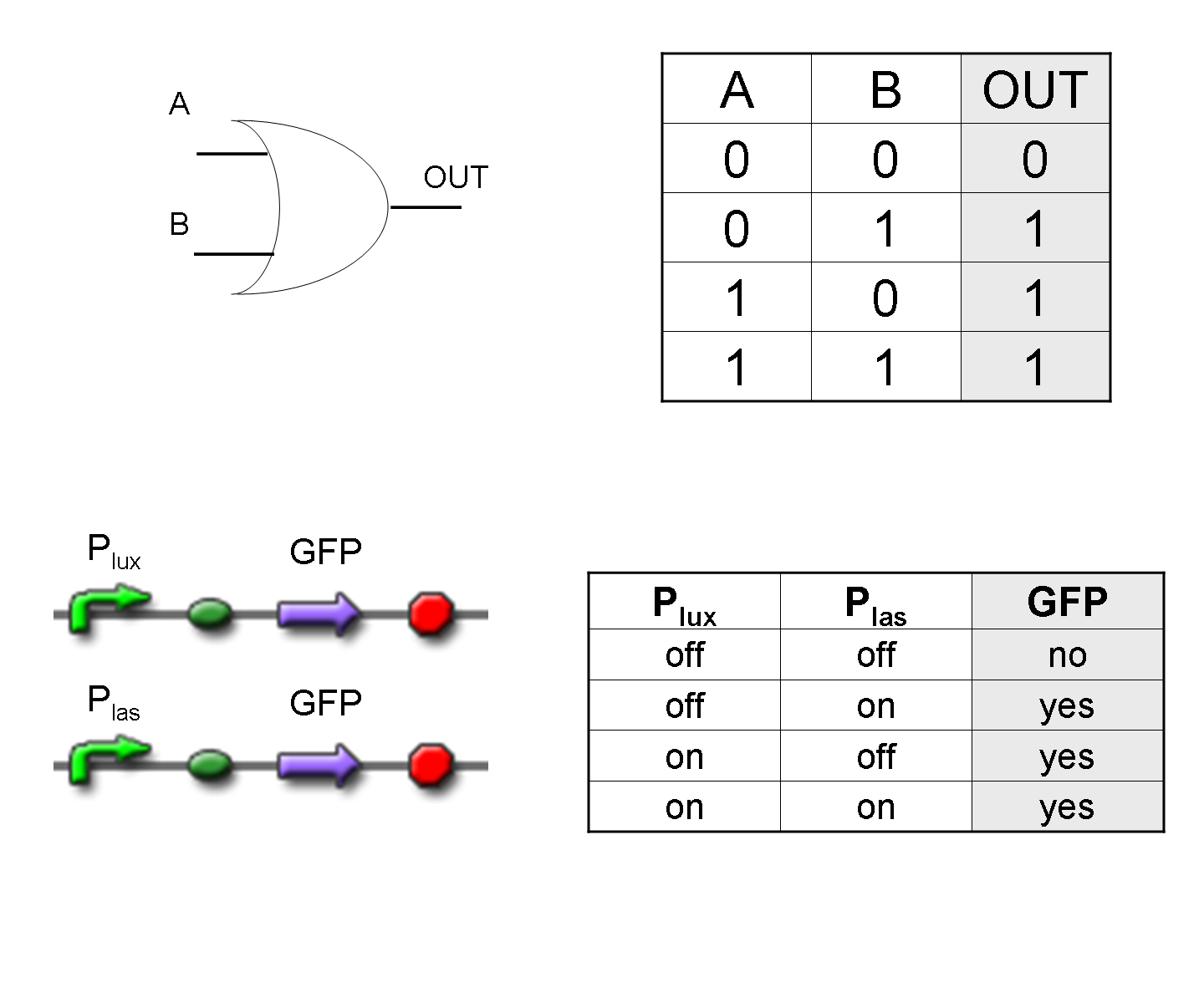
To mimic an OR gate in Mux, we need a biological function which can be activated alternatively by two independent upstream signals or by both. Thus, we combine the outputs of the upstream AND gates to assemble directly an OR reporter function, by simply repeating the reporter gene (GFP) under two different promoters (Plux and Plas). It’s sufficient to activate one of the two promoters (or both) to recover the GFP signal from engineered bacteria. There should not be an over-expression problem for GFP, in fact, in Mux device, only one promoter can be active, either Plux or Plas. Here we considered GFP output, but OR device can be generalized for every output gene.
NOT
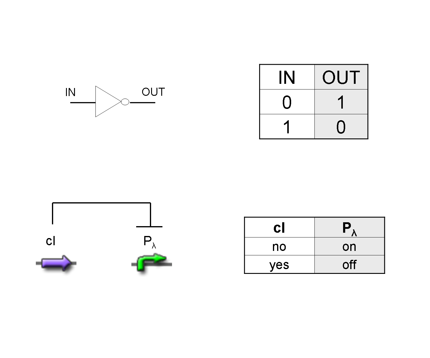
To mimic a NOT gate, we need an efficient and regulated repressor of a specific downstream promoter: in this case, we choose cI repression on Plambda, which should be specific and, upon cI inactivation, quick and efficient.
According to what above stated, genetic implementation of Mux and Demux can be obtained connecting these basic logic gates and can be summarized in this way:
Genetic Mux
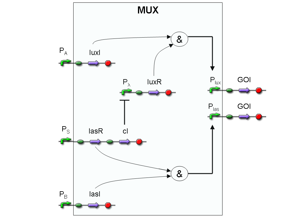
Let PA, PB and PS be three generic promoters that can be ACTIVATED respectively by the three exogenous molecules "A", "B" and "S". A genetic Mux with inputs "A" (CH0) and "B" (CH1), selector "S" and the generic protein GOI as output, can be implemented by the following gene network:
We want to supply a device that can be generalized to detect every kind of input and to express every kind of genes as output. So, input promoters and output protein generators are not part of the genetic Mux we want to build up. In this way, a hypothetical user can re-use our device assembling the desired input and output elements.
Note that the output genes are two, but, as explained in "OR" section, if the genes are identical, we can say that there is only one output; in fact, the real output is a protein synthesis and so it is not important which of the two identical genes is expressed.
However, it is possible to assemble two different genes downstream of Plux and Plas, for example two reporters. In this way, debugging process becomes easy, because we can discriminate lux system and las system activities.
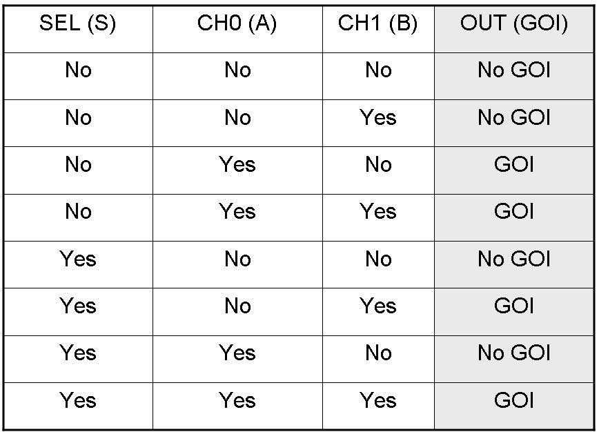
Here we report the truth table of this network:
Now we report two examples of genetic Mux behavior, in response to generic inputs.
Genetic Mux behavior - Example 1
According to Mux truth table, if "A" is not present and "B" and "S" are present, we expect to have GOI synthesis.
"A" molecule is not present, so PA promoter is not active and luxI gene is not expressed.
"B" molecule is present, so PB promoter is active and lasI gene is expressed.
"S" molecule is present, so PS promoter is active and lasR and cI genes are expressed.
cI protein represses transcription of the gene downstream of Plambda promoter, which is luxR.
lasI protein can synthesize 3-OC12-HSL. This molecule activates transcription factor lasR, which can activate Plas promoter. So, the copy of GOI gene under Plas regulation can be expressed.
The other copy of GOI gene, which is under Plux promoter regulation, is not expressed. In fact Plux is not active, because both luxI and luxR proteins are not present.
Only one of the two GOI genes is expressed, but this is sufficient to synthesize the output protein GOI.
Genetic Mux behavior - Example 2
We expect to have no GOI synthesis in response to this input combination.
"A" molecule is not present, so PA promoter is not active and luxI gene is not expressed.
"B" molecule is present, so PB promoter is active and lasI gene is expressed.
"S" molecule is not present, so PS promoter can't transcribe cI and lasR genes.
cI protein is not present, so Plambda promoter can transcribe luxR gene.
None of the two logic AND systems is active, because lux system lacks of luxI and las system lacks of lasR. So, Plux and Plas promoters are unactive and can't express GOI genes. For this reason, GOI protein is not synthesized.
These two examples show how "S" molecule can select the input to convey into the single output channel: in fact its presence allows lasR expression and represses luxR expression, while "S" absence represses lasR expression and allows luxR expression.
Genetic Demux
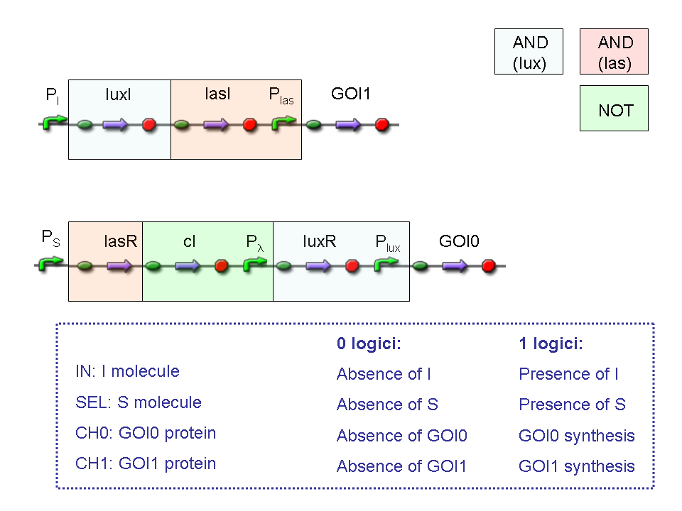
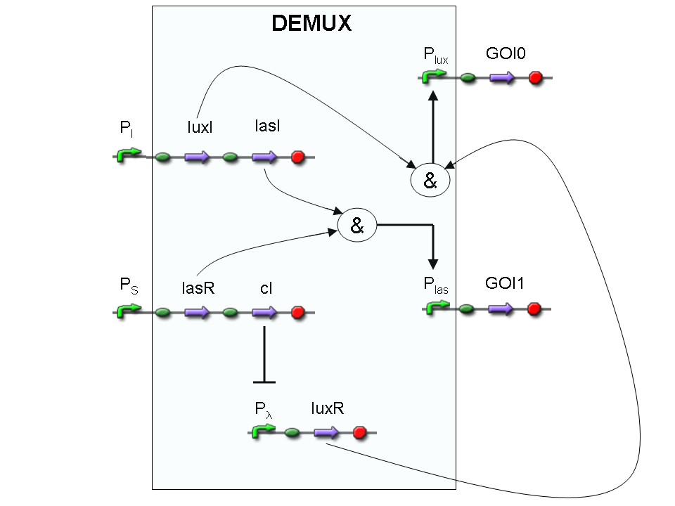
Let PI and PS be two generic promoters that can be ACTIVATED respectively by the two exogenous molecules "I" and "S". A genetic Demux with input "I", selector "S" and the generic proteins GOI0 and GOI1 as outputs (OUT0 and OUT1 respectively), can be implemented by the following gene network:
As described for genetic Mux, we want to supply a device that can be generalized to detect every kind of inputs and to express every kind of genes as output. So, input promoters and output protein generators are not part of the genetic Demux. In this way, a hypothetical user can re-use our device assembling the desired input and output elements.
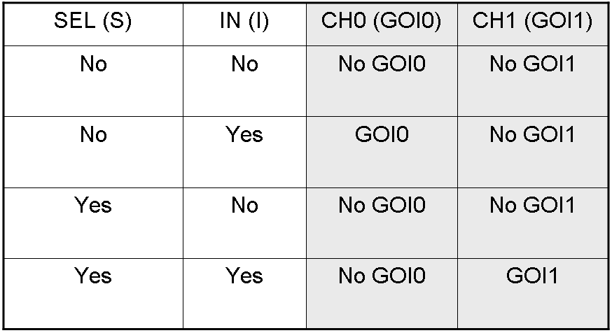
Here we report the truth table of this network:
Now we report two examples of genetic Demux behavior, in response to generic inputs.
Genetic Demux behavior - Example 1
According to Demux truth table, if "I" molecule is present and "S" molecule is absent, we expect to have GOI0 protein synthesis and no GOI1 protein synthesis.
"I" is present, so PI promoter is active and luxI and lasI genes are expressed.
"S" is not present, so PS promoter can't transcribe lasR and cI genes.
cI protein is not present, so Plambda promoter is not inhibited and luxR gene is expressed.
luxI protein can synthesize 3-OC6-HSL lactone. This molecule activates luxR transcription factor which can activate Plux promoter. In this way, GOI0 gene, which is under Plux regulation, is expressed.
On the other hand, lasI protein can synthesize 3-OC12-HSL, but lasR transcription factor is not present and so Plas promoter cannot be activated. In this way, GOI1 gene, which is under Plas regulation, is not expressed.
So, we have GOI0 protein synthesis and no GOI1 protein synthesis.
Genetic Demux behavior - Example 2
We expect to have GOI1 synthesis and no GOI0 synthesis in response to this input combination.
"I" is present, so PI promoter is active and luxI and lasI genes are expressed.
"S" is present, so PS promoter lasR and cI genes are expressed.
cI protein is present, so Plambda promoter is inhibited and luxR gene is not expressed.
lasI protein can synthesize 3-OC12-HSL lactone. This molecule activates lasR transcription factor which can activate Plas promoter. In this way, GOI1 gene, which is under Plas regulation, is expressed.
On the other hand, luxI protein can synthesize 3-OC6-HSL, but luxR transcription factor is not present and so Plux promoter cannot be activated. In this way, GOI0 gene, which is under Plux regulation, is not expressed.
So, we have GOI1 protein synthesis and no GOI0 protein synthesis.
A complete genetic Mux
In this section a complete Mux gene network is described.
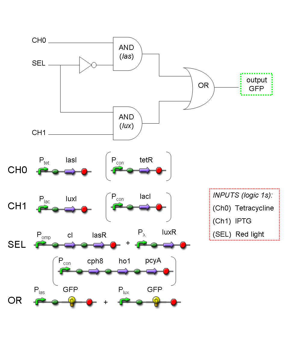
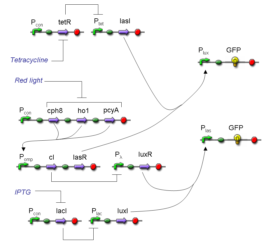
We want to build up a device in which Channel 0, Channel 1 and Selector are respectively sensitive to Tetracycline, IPTG and red light. The presence of each input corresponds to logic 1.
We chose green fluorescence as Mux output: expression of GFP corresponds to logic 1, while absence of fluorescence corresponds to logic 0.
Tetracycline and IPTG can be considered as "A" and "B" molecules, introduced in "Genetic Mux" section, because both Tetracycline and IPTG are indirect ACTIVATORS of Ptet and Plac promoters respectively.
On the other hand, red light is quite different from "S" molecule, because red light is an indirect REPRESSOR of Pomp promoter and not an activator as required by the original schema. For this reason, if we want a device in which the presence of Tetracycline, IPTG and red light correspond to logic 1, red light input should be inverted. The simplest way to do this, is to cross-exchange the two input channels. So, Tetracycline sensor (CH0) has to be assembled to las system and IPTG sensor (CH1) has to be assembled to lux system.
Complete genetic Mux - Example
According to Mux truth table, if SEL=0, CH0=1, CH1=0, output channel must be logic 1. Red light is not present, so it can't dephosphorylate cph8-ho1-pcyA complex, which is constitutively expressed. cph8-ho1-pcyA complex activates endogenous ompR, which can activate Pomp promoter, so cI and lasR genes are transcribed. cI protein binds Plambda promoter and so luxR expression is inhibited. TetR is a repressor for Ptet promoter, but Tetracycline is present, so it can bind tetR protein, which is constitutively expressed, and can activate transcription of downstream gene: lasI. Simultaneous expression of lasI and lasR can activate GFP, which is under Plas promoter. IPTG is not present, so lacI protein binds Plac promoter and represses luxI transcription.
A complete genetic Demux
In this section a complete Demux gene network is described.
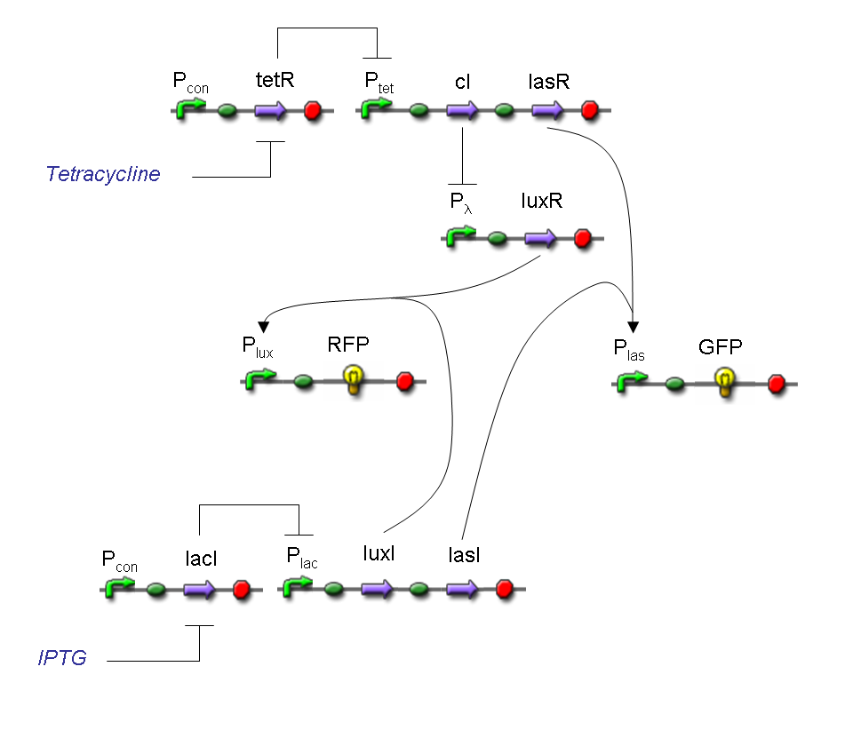
We want to build up a device in which Input and Selector are respectively IPTG and Tetracycline.
In Demux we have two output channels: red fluorescence corresponds to logic 1 at Channel 0, while green fluorescence corresponds to logic 1 at Channel 1.
Absence of reporters expression corresponds to logic 0 at Channel 0 and Channel 1.
There isn't any input combination that corresponds to logic 1 at Channel 0 and Channel 1 together.
Complete genetic Demux - Example
According to Demux truth table, if IN=1 and SEL=1 output channel 0 is logic 0 and output channel 1 is logic 1.
IPTG is present, so Plac promoter is active because IPTG binds lacI protein. This allows lasI and luxI transcription.
Tetracycline is present, so Ptet promoter is active because Tetracycline binds tetR protein. This allows cI and lasR transcription.
cI protein binds Plambda promoter and so luxR expression is inhibited.
Simultaneous expression of lasI and lasR can activate GFP, which is under Plas promoter.
There is no simultaneous expression of luxI and luxR, so RFP (which is under Plux regulation) cannot be expressed.
Final devices
Genetic Mux and Demux have been described by now as systems which are able to detect fixed inputs (IPTG, Tetracycline and red light) and to return a fixed fluorescence (GFP and RFP) as output.
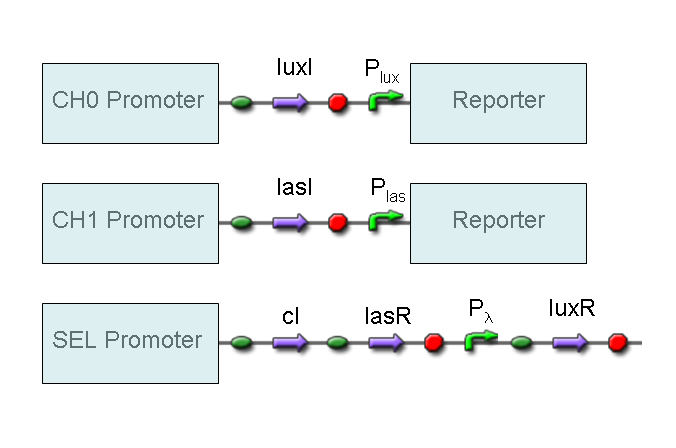
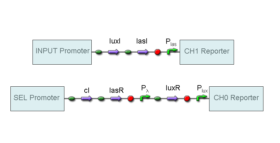
However, our purpose is to supply two devices (Mux and Demux) that can be generalized to detect every kind of input and to return every kind of reporter. To reach this goal, we set up a BioBrick assemble program in which parts corresponding to final devices can be re-used for any kind of input or output.
A hypothetical user of Mux or Demux only has to ligate our standard parts with desired promoters and reporters, as shown in the pictures above.
(In previous paragraphs, Channel 0 and Channel 1 in Mux have been cross-exchanged because red light input inhibits Pomp promoter and so Selector boolean signal is inverted).
 "
"
