Team:UC Berkeley Tools/Project
From 2008.igem.org
The Project
Genomics has reached the stage at which the amount of DNA sequence information in existing databases is quite large. Synthetic biology now is using these databases to catalog sequences according to their functionality and therefore creating standard biological parts which can be used to create large systems.
As these databases grow, the need for integrated tools that perform complex operations, organize information, and automate regular processes is becoming increasingly obvious. The synthetic biology community could be better-served with the development of flexible tools which not only permit access and modification to that data but also allow one to perform meaningful manipulation and use of that information in an intelligent and efficient way. These tools need to be useful to biologists working in a laboratory environment while leveraging the experience of the larger CAD community.
This project develops a toolset called "Clotho" which provides a variety of design views and tools to aid biologists to modify existing synthetic biological systems as well as create new ones. These tools differ from current offerings in this area in that they not only provide the needed tools to manipulate designs in one complete system but also provide unique ways in which to visualize the design as well as a number of connections to both local and global part repositories.
This page provides insight into the background for the Clotho project as rooted in Platform-based design (PBD). PBD provides the overall design methodology for Clotho. This includes the orthogonalization of computation, communication, and coordination. In addition there is a heavy emphasis on reuse and the separation of performance from behavior. Also on this page we provide information regarding the overall timeline of the project, Clotho's software architecture, and a detailed description of all the pieces that go into Clotho.
If there is anything that is not clear here or you want more information, just drop us an email at: clothodevelopment AT googlegroups DOT com. Enjoy!
Platform Based Design
Due to the increased complexity, heterogeneity, and time-to-market concerns currently facing embedded electronic design, the EDA community is facing a crisis. In order to deal with this crisis, a variety of Electronic System Level (ESL) methodologies are emerging. One popular approach is Platform-Based Design (PBD).
PBD is concerned with what is termed the orthogonalization of concerns [1]. These concerns are:
- Functionality (what something does) and Architecture (how it does it). For example, multiplication functionally is the same whether implemented as a series of adders or a dedicated multiplier. This separation goal should be of use as well to synthetic biologists.
- Behavior (Semantics) and Performance Indices (Latency, Throughput, etc). Behavior defines how a device operates (bus protocol for example). Performance is a cost of that behavior (bus transaction latency). Again, this may be of use in describing biological systems.
- Computation, Communication, Coordination. How things compute should be separate from how they interact (communicate) with other aspects of the system, and both computation and communication should be separate from the scheduling mechanisms.
By keeping these issues separate, the now modular design allows for a smoother verification process, reuse, and abstraction. These goals are also of use to the synthetic biological community if predictive, large scale synthetic designs are desired.
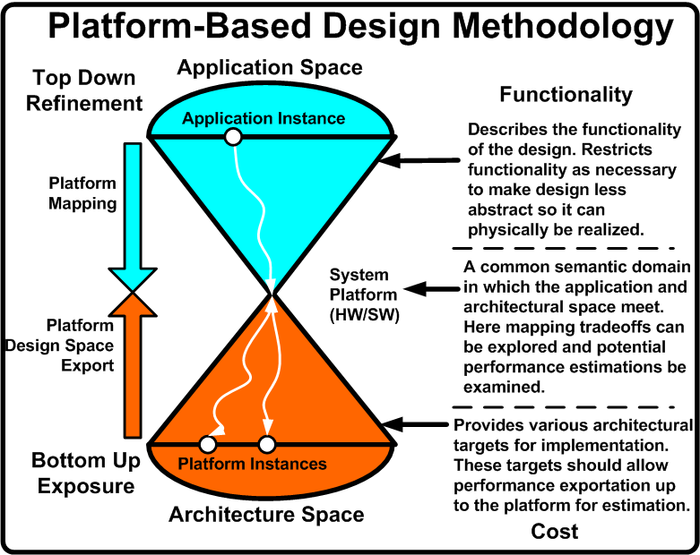
In order to achieve these goals, PBD is a three stage process: top down application development, bottom up performance exposure, and defining a common semantic meeting point to explore functionality and architecture mappings. Figure 1 illustrates this methodology and provides the needed description. [2], [3], and [4] are all successful applications of PBD in embedded electronics.
What follows is a breakdown of the three major aspects of PBD along with how these can be used in the design of synthetic biological systems. For the purposes of the Clotho project, PBD primarily manifests itself in how the software architecture is developed and the role individual pieces play in the overall design.
Functionality
Functionality in PBD purely describes the behavior the desired design should exhibit. It makes no association with the underlying mechanisms that will be used to physically implement the functionality. For embedded electronic systems, models of computation (MoCs) such as Kahn Process Networks, Finite State Machines, Dataflow Networks, Petri Nets, etc are typically used to this end. These are mathematical descriptions which can be analyzed for various properties such as liveness, state reachability, and schedulabilty.
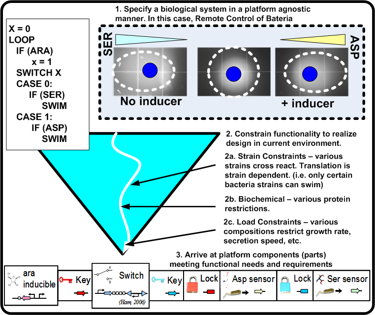
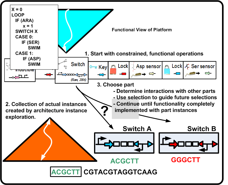
For synthetic biological systems, the ways to describe desired functionality are still in their infancy. For example, while NOR functionality is well understood in a digital logic context, a NOR gate's operation and production in a synthetic biological context depends heavily on the proteins and other chemicals involved. Capturing functional descriptions will prove to be an important part in the development of any design methodology. Figure 2 illustrates a potential process a functional description could go through to constrain itself to map to a platform. Here, Remote Control of Bacteria is shown as a pseudo code initial description. In the event that the inductor Arabinose (ARA) is present, bacteria swim toward Aspartic acid (ASP), otherwise they swim toward Serine (SER). The figure shows the various classes of constraints that direct the functionality toward a particular platform.
In Clotho, functionality is described at the "part" level. For example there may be a number of BioBrick parts each which implement the same function. However they differ in the physical part in the lab which has been created to carry out this functionality. Clotho designs should keep separate the theoretical part from the physical reality.
Architecture
In PBD for electronic systems, architectures provide services which then incur a particular cost if used. The process of selecting an individual architecture instance is then observing which collection of platform components implement the desired functionality at a cost acceptable to the designer (low power, rapid execution time, etc).
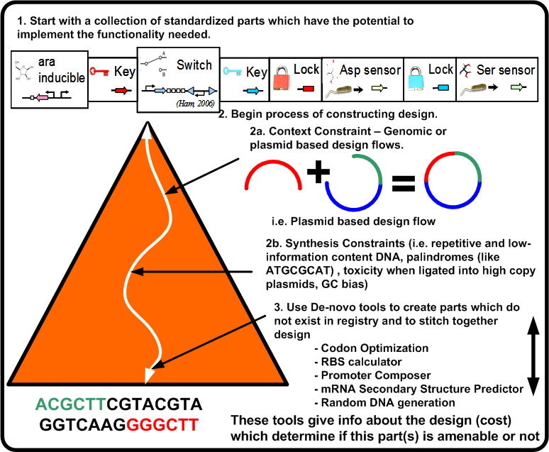
For a synthetic biological system, once the functional pieces have been constrained as shown in Figure 4 what now is required is the actual stitching together of the standardized parts along with synthesizing the needed parts if they do not exist. This leads to the following two points:
- Designs will be composed both of parts which exist in registries as well as DNA synthesized by De-novo tools which fill in the gaps of the design. Parts in registries should be assembled in a standardized way [5].
- Parts must export up cost metrics to allow the design space exploration process to occur. These costs allow decisions to be made regarding the functional assignment to parts (i.e. mapping).
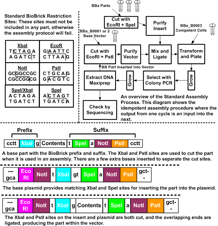
To give an example of such a stiching assembly method, Figure 3 illustrates how this is done for the BioBricks system. The BioBricks parts are comprised of their contents, and standard BioBricks ends. The contents are arbitrary, with the caveat that they may not contain any of the BioBricks restriction sites (EcoRI, XbaI, SpeI, NotI and PstI). These sites can be mutated out through manual edits of the sequence. In most cases, changes can be made that do not affect the system due to the redundancy in the codon specificity. The prefix for a part is a cctt +XbaI + g site, and the suffix is a t + SpeI + a + NotI + PstI + cctt. The restriction sites enable the idempotent construction, while the extra bases help to separate restriction sites and allow the enzymes some overhang at the ends.
Parts are grown and stored in plasmid vectors. These vectors are circular pieces of DNA that bacteria exchange with each other. There is a set of standard BioBrick plasmids that are used to build and grow parts. They contain sites that enable the introduction of the BioBrick parts.
To put parts together, we cut the parts with the appropriate restriction enzymes and then ligate the cut products together. In Figure 3, we place one part on the beginning of another part.
The key to the idempotent assembly process is the convenient nature of the XbaI and SpeI sites. The overhang is identical, but the ends of each cut site are different, so the combined site can be ligated, but not cut. Yet, the ends remain the same, and thus, we can compose parts again and again.
For the component that we are prepending, we take the DNA and cut it with EcoRI, and XbaI. The component we are inserting is cut with EcoRI and SpeI. These components are then ligated together and the result is the combined part, with the same ends, but with an uncuttable mixed SpeI/XbaI site where they were ligated.
Figure 4 illustrates the constraints which take the potential parts of the biological platform for a given functionality and compose them to an actual design instance (DNA sequence). This requires a number of steps in which the design becomes closer to implementation while at the same time updating the overall cost of the design.
Clotho will provide a means by which functionality (BioBrick based designs) can be realized as physical implementations via the support of assembly algorithms which not only provide valid assemblies of standardized parts, but also provide efficient optimized assemblies which minimize the design steps and stages needed. This will help save both time and money associated with standard part assembly.
Mapping
Once the functional description has been constrained and the architecture instance costs determined, the mapping process becomes one of selecting functionality and assigning it the services provided by the architecture instances. This is only possible once those two steps have been done such that both spaces are specified in the same semantic domain [6]. This happens at a variety of abstraction levels. In electronic system design, a more abstract level may include the assignment of services such as execute, read, and write to an ALU and memory interfaces respectively. A lower level of abstraction may assign a 4-input AND operation to either a single 4-input AND gate or to a collection of three 2-input AND gates as a simple two level logic circuit. The selection of a final mapping is based on the resulting costs and the designer's objectives (i.e. the a single 4-input AND may have a smaller area requirement than three 2-input ANDs).
Mapping in synthetic biology is a complex process. Not only does one need to assign functionality to available DNA sequences but the assignment of functionality to a sequence may either preclude or enhance the selection of functionality to other parts available to the design. Specific mappings may create chemicals not present in other mappings, express genes with a higher or lower probability, and react faster or slower in the given environment. A mapping tool should attempt to predict these relationships when possible and highlight parts which make a given mapping more likely to be successful in practice. Figure 5 illustrates mapping issues.
Clotho will provide the ability to create user designed plug-ins which will help bridge the gap between the functionality desired and the many ways in which it can be physically implemented. A large part of the future work in Clotho will be design views which allow designers to test tradeoffs between the assignment of various BioBricks to specific functional portions and to view the tradeoffs of such decisions.
Project Architecture
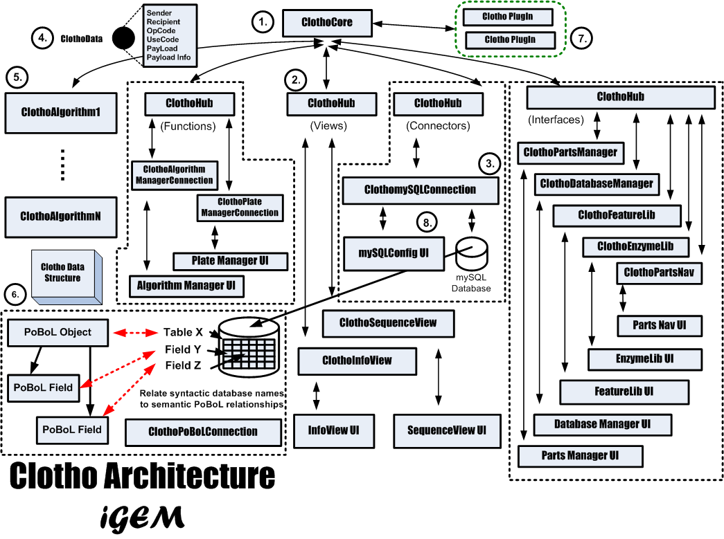
Orthogonalization of concerns is the separation of communication, coordination, and computation as described by PBD. This aids in reuse, debugging, and system analysis. The added modularity allows for system expansion as well as configurablity. Therefore each aspect of the Clotho system is classified as to what type of operations it is involved with and the communication between components is explicitly separated from the computation of each component. The coordination of the system is also removed from each individual component and maintained in a central location. Figure 6 illustrates Clotho's overall system architecture.
Clotho is based on a core-and-hub system which manages multiple connections, in which each connection serves an independent purpose in a self-sufficient manner. For instance, while one connection may be in charge of viewing/editing a sequence in an [http://www.biology.utah.edu/jorgensen/wayned/ape/ ApE]-based manner, another connection may connect to databases, and will allow the user to receive and submit parts. Each connection may also perform more integrative tasks by passing data to each other through the core. If a user were working through the sequence view and database manager, for example, then the two connections could talk to each other if the user wished to edit a part in the sequence view and then resubmit the part back to the database.
Also of interest is the separation of the individual user interfaces from the connections which provide the functionality. In this way, if the look and feel of Clotho is not right for a particular user, it is much easier for them to create a new visual interface while still reusing the underlying code.
There are many aspects to Clotho shown in Figure 6. The following sections will describe each of these pieces of Clotho in more detail.
Project Details
Overall Timeline
The Clotho project has its roots in initial conversations between Douglas Densmore and Prof. Chris Voigt at UCSF in the summer of 2007. From these initial meetings it became clear that there was a need for a system to design, manage, and deploy systems based on standard biological parts. This section provides some insight into the progression of this process.
- iGEM 1st Meeting: June 2, 2008 - Nade and Matt start working on the first official Clotho connections (Help and About connections).
- Full Team Assembled: June 9th, 2008 - Anne Van Devender arrives from Washington and Lee University as part of Berkeley's SUPERB summer research program.
- Officially Sync Up with Wet Team: June 16, 2008 - Comp team meets with Prof. J. Christopher Anderson to talk about the overall goals of the project and how to best meet the needs of the wet team.
- Meet the Press: July 7, 2008 - Official photo shoots for both future wiki material as well as [http://blogs.coe.berkeley.edu/igem UC Berkeley's College of Engineering Blog]
- Clotho Testing Session 1: July 14, 2008 - Full testing session of Clotho with members of the wet team.
- Clotho Testing Session 2: July 16, 2008 - Second full testing session of Clotho with members of the wet team.
- Clotho Alpha Release: July 26, 2008 - [http://biocad-server.eecs.berkeley.edu/wiki/index.php/Clotho_Development Download Here.]
- Adjustment in Team Personnel: August 1, 2008 - Anne Van Devender returns to Washington and Lee University.
- Clotho iGEM Release: October 29, 2008 - Official release of Clotho for iGEM made public.
- iGEM 2008 Jamboree: November 8-9, 2008 - TBD???
1. Clotho Core
The ClothoCore object (#1) in Figure 6 maintains control over the hubs and (by implication) the connections in the system. The core is responsible for routing ClothoData objects to the correct hub. The core is also responsible for setting up initial connections in the system. The core has both a hub and connection addressing scheme. This system allows for the core to know both how to address a connection in a hub as well as where connections are without having to directly speak to the hub. This bypassing is useful if general system information needs to be queried or to perform common operations faster. For example, once a connection has been contacted by the core, it then can initiate a transaction back to the core in response to the sender of the data. The core can store the information about this link and therefore prevent redundant setup information to be repeatedly passed back in forth in the event that each connection wants to transfer more than one ClothoData object. This can occur as long as needed to finish the transaction. This is similar to direct memory access (DMA) transfers in computer architecture.
Because of the modular way in which Clotho has been designed, a developer wishing to use Clotho need only create a connection derived from one of the 4 basic types of connections. Once the connection has been defined, it need only be instantiated in the Clotho main file and then call the required activate method. The ClothoCore takes care of the rest. Activation of a connection associates it with the core, a specific hub, provides it a global and hub address, and runs any needed start up routines. The core is used to not only activate connections but it can also run regular start up operations, load preference data on start up, and save preference data to various files in the Clotho system.
For more detailed insight into the core's operation you can check out the java doc here.
2. Clotho Hub
To make the location and management of connections easier, connections are grouped and linked to ClothoHubs (#2) in Figure 6. Like connections, hubs are categorized as view, interface, connector, and function. There is one type of each of these hubs in the system. Connections belong to one hub each and belong to the hub corresponding to the type of connection they are derived from. Hubs maintain a list of all connections they are responsible for and provide information about these connections to the ClothoCore during initialization. This information includes the hub address of the connection and connection abilities. Hubs allow for not only point to point communication between connections but also can broadcast a single ClothoData object to all the connections of the hub. This is useful if an application wishes to send one piece data to multiple connections simultaneously. All hubs are connected to one ClothoCore.
For more detailed insight into the operation of a hub you can check out the java doc here.
3. Clotho Connection
ClothoConnections are the workhorses of the system. They represent the computational aspect of PBD. Connections are categorized as view type, connector type, function type, and interface type. View connections deal with the display of biological information. This can be both graphical or textual. Views may also present (push) system information to the user. Connector type connections connect Clotho to external tools or data sources. Function connections are processing engines for data. Interface connections are points of interaction for the user to control the operation or settings assigned to Clotho. Interface connections can also manage libraries which Clotho uses. An example of a ClothoConnection is marked by (#3) in Figure 6. Notice that connections are explicitly separated from the user interface (UI). This allows complete aesthetic overhauls of Clotho without having to modify the connections.
ClothoConnections are by far the most prevalent objects in the system. They are derived Java classes which inherent methods to process data, communicate with other connections, display information to specific debugging sources, group themselves with other connections, and to make themselves explicitly available to the user via a Java Swing GUI interface. Key to the operation of ClothoConnections, is the ClothoData object which will be described next.
For more detailed insight into the operation of the connections you can check out the java doc here.
4. Clotho Data (Generic)
In Figure 6, (#4) marks a ClothoData object. ClothoData objects are the means by which ClothoConnections communicate with one another. ClothoData objects are classes encapsulating the following information:
- Sender - The connection which generated this object. This is the connection which is typically initiating a transaction.
- Recipient - The intended destination for this object. This is the connection which is typically responding to a transaction.
- Op Code and Use Code - These codes determine the type of operation which the data should be used for (e.g. calculate a DNA sequence's open reading frames) as well as how it should be used within the operation itself (e.g. the data is the sequence itself). There are an explicit enumeration of both Op Codes and Use Codes which enforce type safety in the system.
- Payload - This is the bulk of the data. This is a generic data object which allows the system to pass back and forth whatever is required for the transaction.
- Payload Information - An additional mechanism for detailing the payload should the Op and Use codes not be sufficiently granular.
Each individual connection is responsible for both being able to generate their own ClothoData objects and well as process incoming data objects. ClothoData objects are routed throughout the system by a connection addressing scheme. A key aspect of this addressing scheme is a ClothoHub.
For more detailed insight into the organization of a Clotho Data object and its operation you can check out the java doc here.
5. Clotho Algorithm
In addition to connections, Clotho also supports ClothoAlgorithms. These interact specifically with the Clotho Algorithm Manager. These are shown as (#5) in Figure 6. This specific connection makes user created algorithms available to the rest of the system. The user can create an extension of the ClothoAlgorithm class and simply instantiate the algorithms in the Clotho software architecture netlist and register them with the ClothoCore. This then makes the algorithm available to use through a flexible GUI. The algorithm manager also allows the algorithms access to any of the database connections available to Clotho. This can be used to look up part information or save and create new parts.
For more detailed information on the algorithm manager and the creation of algorithms you can check out the java doc here.
6. Clotho Data Structure
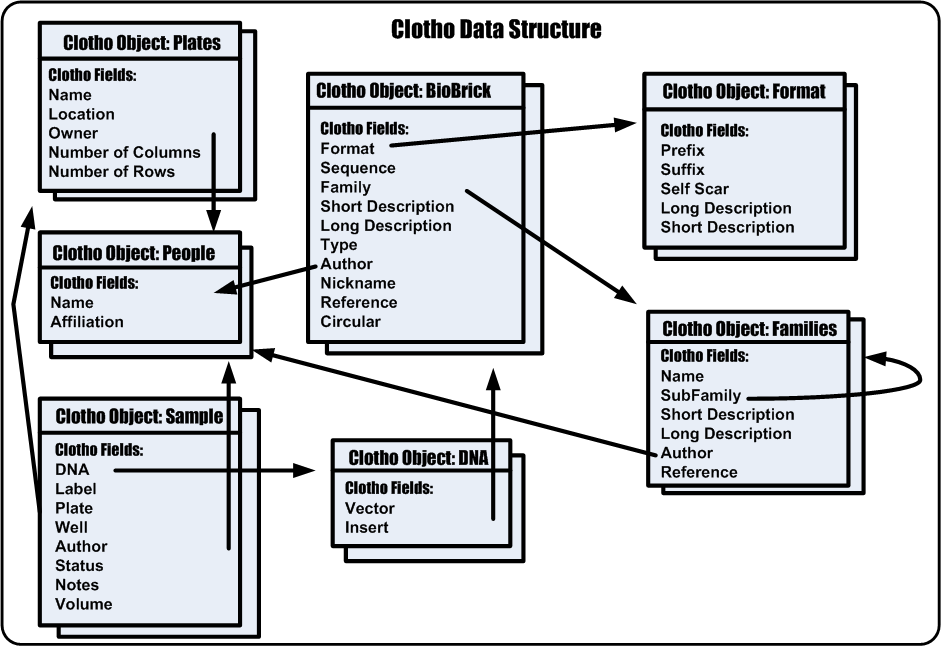
The purpose of the Clotho Data Structure is to take potentially random, unorganized data and give it both syntactic and semantic meaning. Once this process has been done Clotho can now work on data in a unified framework by which developers and users can speak the same language about design. The Clotho Data Structure is shown as (#6) in Figure 6. A more specific view is shown in Figure 7.
To begin, the Clotho data structure has both Objects and Fields. It has a finite set of objects defined currently in a manner very similar to [http://www.pobol.org PoBoL]. These objects include:
- BioBricks
- DNAs
- Samples
- Plates
- People
- Formats
- Families
Each object has a number of fields that can be assigned to it. An example of some of these fields include:
- Nickname
- Short Description
- Long Description
- Author
- Sequence
The number and types of fields associated with the object depend on the object itself. The data structure is modular so that the number and types of objects can increase or decrease as well as the field number and type. Fields are also designated as data or references. Data fields are information about the object while reference fields are pointers to other objects.
The Clotho Data Structure becomes functional when real world data is assigned to the Clotho Data Structure. This is a syntactic binding process where database tables are assigned to Clotho Data Objects and their fields are assigned to Clotho Data fields. It is in this way that potentially un-organized data becomes organized.
Bindings are kept in a binding file and have the following structure:
<Database table>;<Database field>;<Pobol Object>;<Pobol Field>;<Data or RefKey><Ref Table>
Examples:
Samples;Plate_id;Samples;Plate (ref key);RefKey;Plates
BioBricks;Nickname;BioBrick;Nickname;Data
When Clotho wants to perform operations on data, it no longer has to understand anything about the original data source and only rely on its standard data model. This is true also of plug-ins to Clotho. Plug-in developers need not learn about the structure of any external data sources but only develop algorithms and tools which speak to Clotho. Clotho has leveraged a PoBoL like organization to make it as accessible as possible to a larger community.
For more detailed insight into the semantics of the Clotho Data Structure you can check out the java doc here.
7. Clotho Plug In
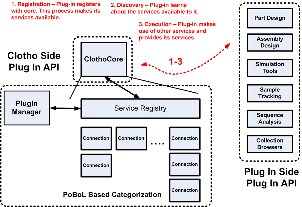
Figure 8 shows a more detailed illustration of the Clotho Plug-in environment.
For more detailed information about the plug in environment for Clotho and to download plug-ins you can check out [http://biocad-server.eecs.berkeley.edu/wiki/index.php/Clotho_Development#Plug-Ins this page].
8. Clotho User Interfaces
In Figure 6 (#8) illustrates that the actual user interfaces from Clotho are kept separate from the connections which implement their functionality. This allows for changes to be made quickly to the look and feel of the tool without having to change code relating to the operation of the system. The following individual sections provide screenshots of the individual user interfaces as well as a feature list for each.
Main Toolbar
The main toolbar is the primary point of interaction for Clotho. The main toolbar allows the user to interact with other Clotho "Connections". The toolbar supports the following features:
- Set the skin for Clotho. Using the "Substance" look and feel library the user can set the skin of the tool.
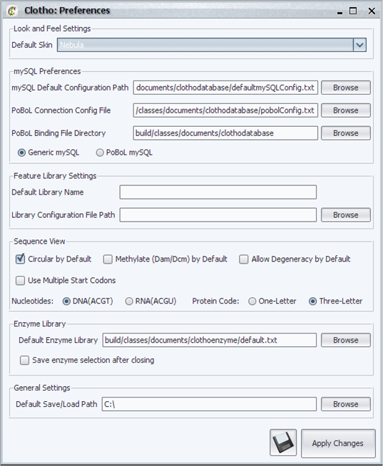
- Set the preferences. The user can define the preferences for the tool. These include (amongst other things) the default location of various configuration and library files, the default skin, and which nucleotide characters are allowed in the sequenceview.
- "Trigger" (use/open) connections related to IO (Connector connections), Tools (Function connections), Views (View connections), Interfaces (Interface connections).
- "Populate" the drop down menus with the latest activated connections*.
Shown are screen shots of the preferences and main toolbar windows. Closing the main toolbar will allow the user to exit the Clotho program.
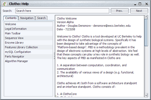
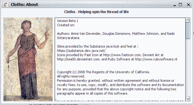
From the main toolbar there are also "Help" and "About" windows available to provide information about Clotho to the user.
mySQL Configuration Manager
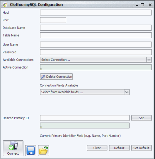
The mySQL configuration manager allows the user to:
- Connect to mySQL databases.
- Manage the connections that they have made (set the connections as the "active connection" or deleting connections).
- Load and Save the current configurations.
- Load and Set the default configuration.
- Set the primary identification used by the parts navigator to display and organize parts.
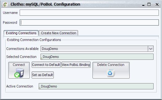
mySQL/PoBoL Configuration Manager
The mySQL/PoBoL configuration manager allows the user to connect to a mySQL database with the intention of binding tables and fields in that database to the Clotho Internal Data Structure. It has the following features:
- Ability to create new connections and manage a collection of connections (e.g. set default connection, connect to a particular connection, and delete connections).
- Ability to view the binding file for a particular connection.
- Ability to view the currently active connection.
PoBoL Binding Manager
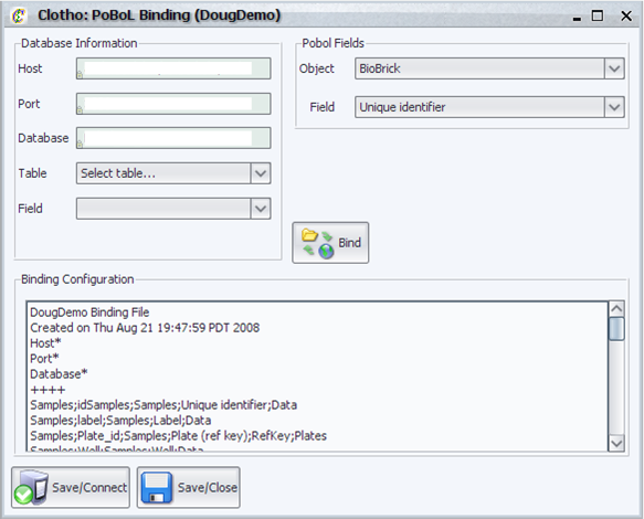
The PoBoL binding manager creates a binding file for each connection created by the mySQL/PoBoL connection interface. A binding file creates a correspondence between a table in a database and a Clotho Data Structure Object. For example table Parts in a generic database may be bound to the Clotho Data Structure object BioBricks. In addition it creates a correspondence between fields in a table and Clotho Data Structure fields belonging to object. For example table Parts->Data may correspond to BioBrick->Sequence. In order to create this binding the binding managers supports:
- The ability to view the host, database, and port associated with a connection.
- The user can assign database tables to Clotho Data Objects and database table fields to Clotho Data Fields.
- Automatically recognizes database references and prompts the user to their existence. This allows hierarchy in the database.
- The user can directly modify the binding file if the automatic methods are not sufficient for their needs.
- Save and connect support for the binding file being created.
Info View
The Info View displays messages (and the number of messages) in three different categories:
- Messages - information about the general operation of the system.
- Warnings - information about operations that have been denied but still allow future system operation.
- Errors - information about operations that have been denied and will prevent future system operation unless resolved.
Each window can be cleared individually or collectively.
The parts navigation system allows the user to browse parts related to a remote parts repository. This system consists of three aspects:
- Parts Navigator - tree view for parts.
- Parts Information Windows - information on a specific part.
- Parts Packager - way to package design data as a part to be saved to a repository of the designer's choosing.
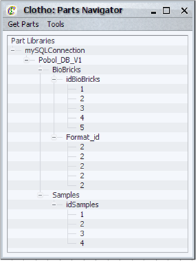
The parts navigator is a hierarchical, tree based viewer for parts. The user can:
- View parts from a particular active connection as set in the mySQL configuration.
- Refresh selected part trees with the latest data for the appropriate connection.
- Refresh all part trees with the latest data from their individual connections.
- Connect to mySQL based repositories.
- Connect to to XML based data repositories*.
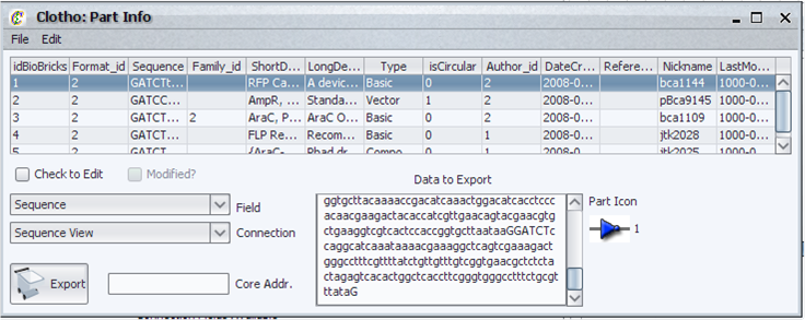
The parts information view allows the user to:
- View the part information.
- Edit the part information and save it to the database it was retrieved from.
- Add new parts to databases.
- Submit single parts or groups of parts.
- Delete parts from databases or just from the part viewer.
- View the icon associated with the part.
- Export selected part information to other Clotho Connections*.
- Associate an icon with the part*.
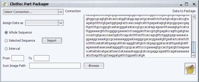
The parts packager allows the user the user to package the data from the sequence view as a part. The user can:
- Select a connection to associate the newly created part with from the list of active connections in the system
- Select a field in the associated connection to associate the data with
- Export the part to the connection so that the user can submit to the database
Parts Manager
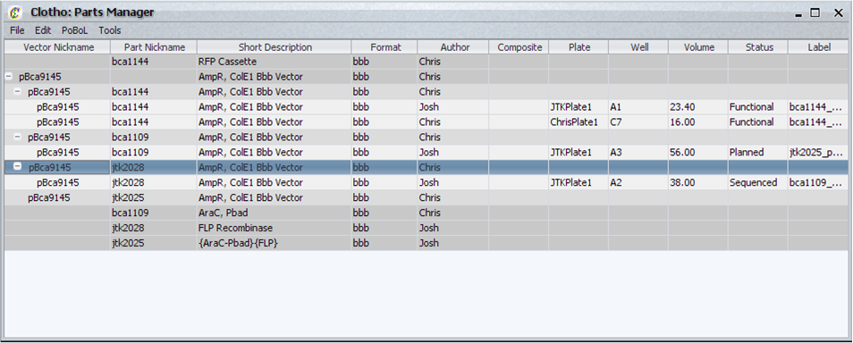
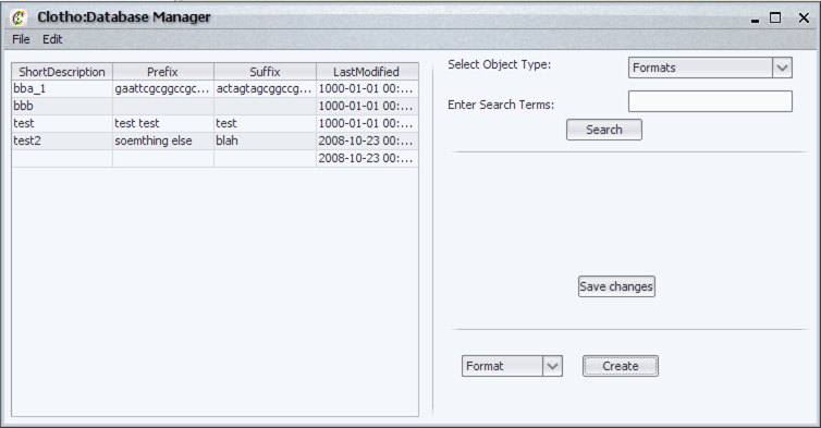
The Parts Manager allows you to view and add parts from any database connected to the Clotho data model. After connecting to a database by the Database Manager (below), the Parts manager once initiated checks to see if all bindings have been created within the Clotho binding file. It holds the following features:
- Displays parts according to BioBrick, DNA, and Sample levels, all placed in its respective hierarchy.
- Allows editing of parts to local view
- Allows editing of parts to lab databases (*)
- New parts may be added to the local view
- New parts may be added to lab databases (*)
- Can access collections of parts belonging to different people in the lab (*)
Database Manager
Algorithm Manager
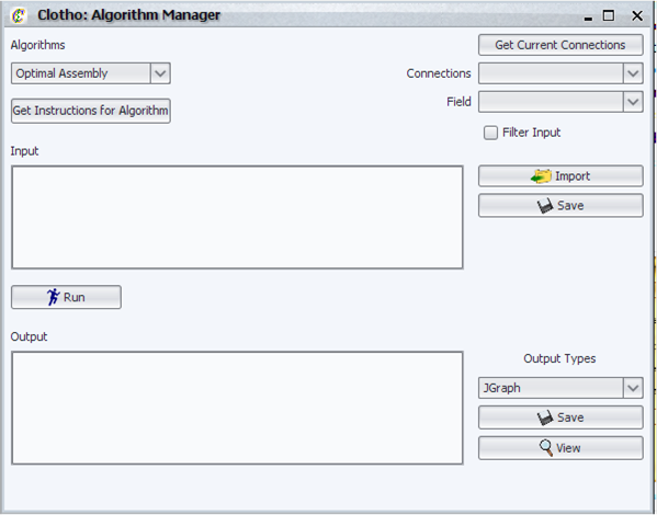
The Algorithm Manager is a graphical user interface which allows the use of various algorithms available in Clotho. Its primary features are:
- Interact with different algorithms - Clotho dynamically detects which algorithms are available to the user and provides the ability to select and view instructions on a per algorithm basis.
- Import input from files - read input from a previously saved file.
- Import input from any database configured in the "mySQL Configuration Manager" - any part in a active mySQL Clotho connection can be imported and translated to the format required by the algorithm.
- Save input for later use - input can be saved to a file of the user's choice.
- Save output in any format permitted by the selected algorithm - the algorithm dynamically provides the user with a list of output file types it supports.
- View that output by loading the appropriate program from your desktop - this includes opening external programs as well as Clotho specific views**.
- A user may also implement their own algorithm in Clotho with only a few lines of code - this code is minimal and java docs are provided to allow the user to do so*.
The alpha and iGEM versions of Clotho comes with an optimal assembly algorithm without taking into consideration common sub-parts as well as an algorithm using various heuristics to assembly standard parts taking into account antibiotic resistance markers in the vector.
Enzyme Library
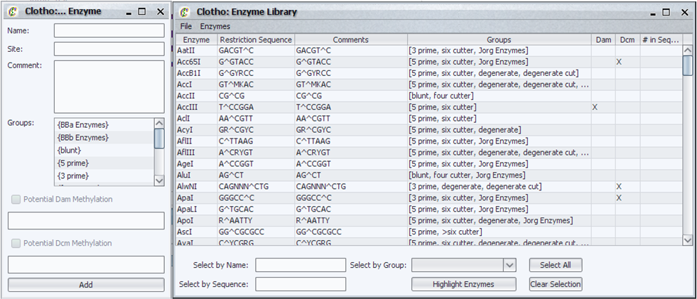
The Enzyme Library allows the user to interact with and utilize a library of restriction enzymes for various functions in Clotho. The user can:
- Select and search for any number of restriction sites in the Sequence View
- Find unique restriction sites in a sequence
- Search the enzyme library for specific enzymes by name and sequence
- Specify groups of enzymes for easy selection and highlighting later
- Add or delete enzymes on the fly
- Create entirely new libraries or load ones created by other users
Sequence View
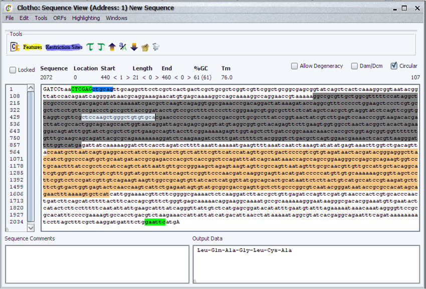
The Sequence View is the primary view for all nucleotide sequences. A wide variety of functions and processes are available, including:
- Basic DNA analysis functions such as protein translation, finding open reading frames (in both the sequence and its reverse complement), percent G-C content
- The ability to automatically search for and highlight multiple features and restriction sites, even when they overlap.
- The choice of using IUPAC degenerate codes in the sequence and remain fully compatible with feature, restriction site, and other searches
- Loading from and saving to files in FASTA and Genbank-based formats
- The ability to track changes in the sequence, to allow multiple-step undo and redo operations
- Edit operations such as moving the origin of circular sequences, cut, copy, and pasting sequences and their reverse complements, and the ability to change the case on nucleotides for easier reading of features
- The ability the manage multiple Sequence View Windows at once, in order to manipulate multiple sequences
- Packaging sequences as "parts", which can subsequently be used to create more complex "composite parts" out of out of multiple sequences, or just submitted to a part database for future use.
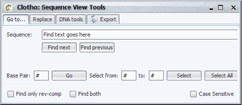
The tools menu provides some functionality in addition to the main Sequence View, such as:
- Go-to functions for finding specific locations within sequences
- Search and replace functions with the ability to search for reverse complements
- Tool bar for performing functions on sequence data
Feature Library Collection
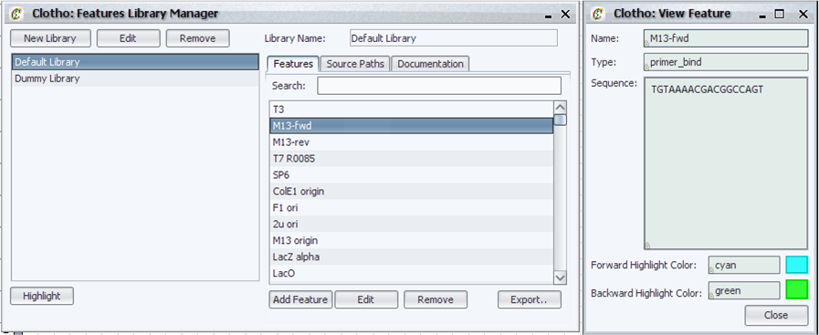
The Features Library Collection contains all the feature libraries for Clotho. The user can:
- Highlight features, including matching with degenerate sequences
- Create, edit, and remove custom feature libraries
- Contain multiple source files and individual features in one library
- Create, edit, and remove non-source file-associated individual features with Clotho’s user-friendly New Feature Wizard
- Search for features using the quick search bar above the features list
- Export feature libraries to ApE readable format
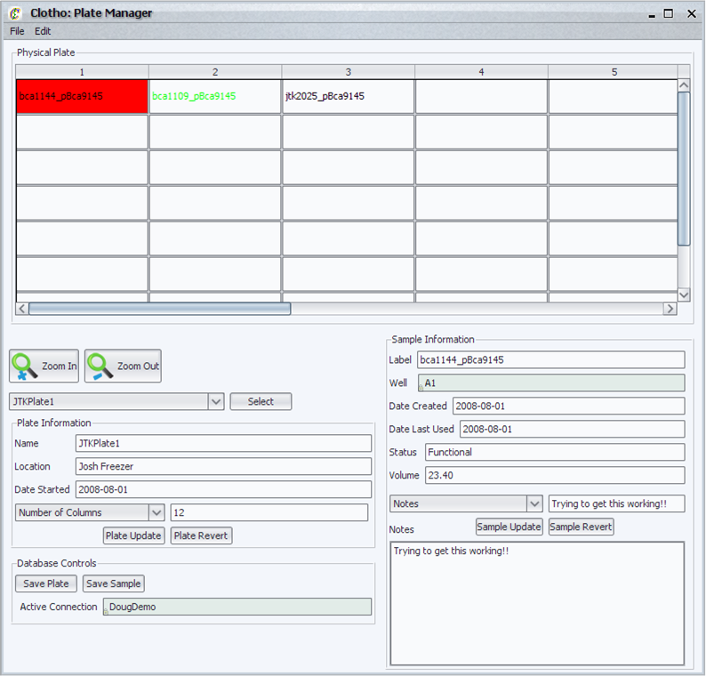
Plate Manager
The plate manager is a link between the theoretical world of biobricks and the physical world of the laboratory environment. This is a virtual plate where the user can:
- View all plates currently available to the user in the database connection.
- Select samples and view information dynamically from the database.
- Zoom in and out of the plate.
- Preferences allow the user to set what information is displayed about the plate and sample.
- Preferences also allow the user to set conditions to color both the well text and the well color depending on sample information.
- The user can update sample information to the database directly.
References
- K. Keutzer, S. Malik, R. Newton, J. Rabaey, and A. Sangiovanni-Vincentelli. System level design: Orthogonolization of concerns and platform-based design. IEEE Transactions on Computer-Aided Design of Integrated Circuits and Systems, 19(12), December 2000
- F. Balarin, Y. Watanabe, H. Hsieh, L. Lavagno, C. Passerone, and A. Sangiovanni-Vincentelli. Metropolis: An integrated electronic system design environment. Computer, 36(4):45–52, 2003.
- D. Densmore, S. Rekhi, and A. Sangiovanni-Vincentelli. Microarchitecture development via metropolis successive platform refinement. In Design Automation and Test in Europe (DATE), February 2004.
- A. Davare, D. Densmore, T. Meyerowitz, A. Pinto, A. Sangiovanni-Vincentelli, G. Yang, H. Zeng, and Q. Zhu. A next-generation design framework for platform-based design. In Conference on Using Hardware Design and Verification Languages (DVCon), February 2007.
- T. F. K. Jr. Idempotent vector design for standard assembly of biobricks. Technical report, MIT AI Lab, 2002.
- Q. Zhu, A. Davare, and A. Sangiovanni-Vincentelli. A semantic-driven synthesis flow for platform-based design. In submitted to Fourth ACM-IEEE International Conference on Formal Methods and Models for Codesign (MEMOCODE’06), July 2006.
[*] Not fully functional in the iGEM release.
[**] The optimal assembly algorithm provided with the iGEM release allows the user to view assembly graphs.
 "
"
