Team:Harvard/Hardware/MFCProcedure

From 2008.igem.org

(Difference between revisions)
m
m
Line 76: Line 76:
* 1' Titanium Grade 2 Wire .046" Diameter
* Teflon Tape, 1/4" Width
-
* 6" x 3" Silicone Sheet
+
* 5" x 2.5" Silicone Sheet
* Silicone Glue
* Silicone Glue
* Spiral Point Tap 1/4"-28
Line 96: Line 96:
#* Squirt 2mm thick line of silicone on edge of tube (edge furthest from holes)
#* Press tube firmly against marked location on endplate
-
#* Quickly use plastic spatula to spread excess silicone along edge
+
#* Quickly spread excess silicone along edge
#* Let stand 24h to harden
[[Image:glued_half.jpg | 600px]]
[[Image:glued_half.jpg | 600px]]
 +
# Construct Gaskets
 +
#* Cut silicone sheet into two equal 2.25" x 2.25" pieces
 +
#* Cut out centered inner squares in each piece, 1.75" x 1.75"
 +
#* Using inner squares, cut two 'O' rings, inner diameter 1/4", outer diameter 1/2"
 +
[[Image:gaskets.jpg | 600px]]
 +
# Construct Electrodes
 +
#*
 +
#*
 +
[[Image:electrodes.jpg | 600px]]
-
 
+
# Seal Injection Ports
 +
#*
 +
#*
 +
[[Image:fin_chamber.jpg | 600px]]

Revision as of 21:57, 29 October 2008


Running an MFC Experiment

This page is intended as a comprehensive guide to completing a microbial fuel cell setup and running an experiment from start to finish.

Creating a Testing Environment

Begin 1-2 weeks prior to experiment

Constructing Fuel Cell Components

Materials (per fuel cell)

  • 4" Polycarbonate Square Tube, 2" Outer Diameter
  • 6" x 6" Polycarbonate Sheet, 1/4" Thick
  • 4 Steel Fully Threaded Stud, 1/4"-20 Thread, 6" Length
  • 8 Zinc Alloy Wing Flange Nut, 1/4"-20 Screw Size, 1" Wing Spread
  • 1" x 1" Nafion® membrane, 0.180mm thick
  • 1" x 1" Carbon felt, 0.25" thick
  • 1" x 1" E-TEK ELAT™ GDE (platinum on carbon)
  • 1' Titanium Grade 2 Wire .046" Diameter
  • Teflon Tape, 1/4" Width
  • 5" x 2.5" Silicone Sheet
  • Silicone Glue
  • Spiral Point Tap 1/4"-28
  • 8 Plastic Luer Lock Coupling Nylon, Female to Male Thread, 1/4"-28

Procedure

  1. Mill Polycarbonate
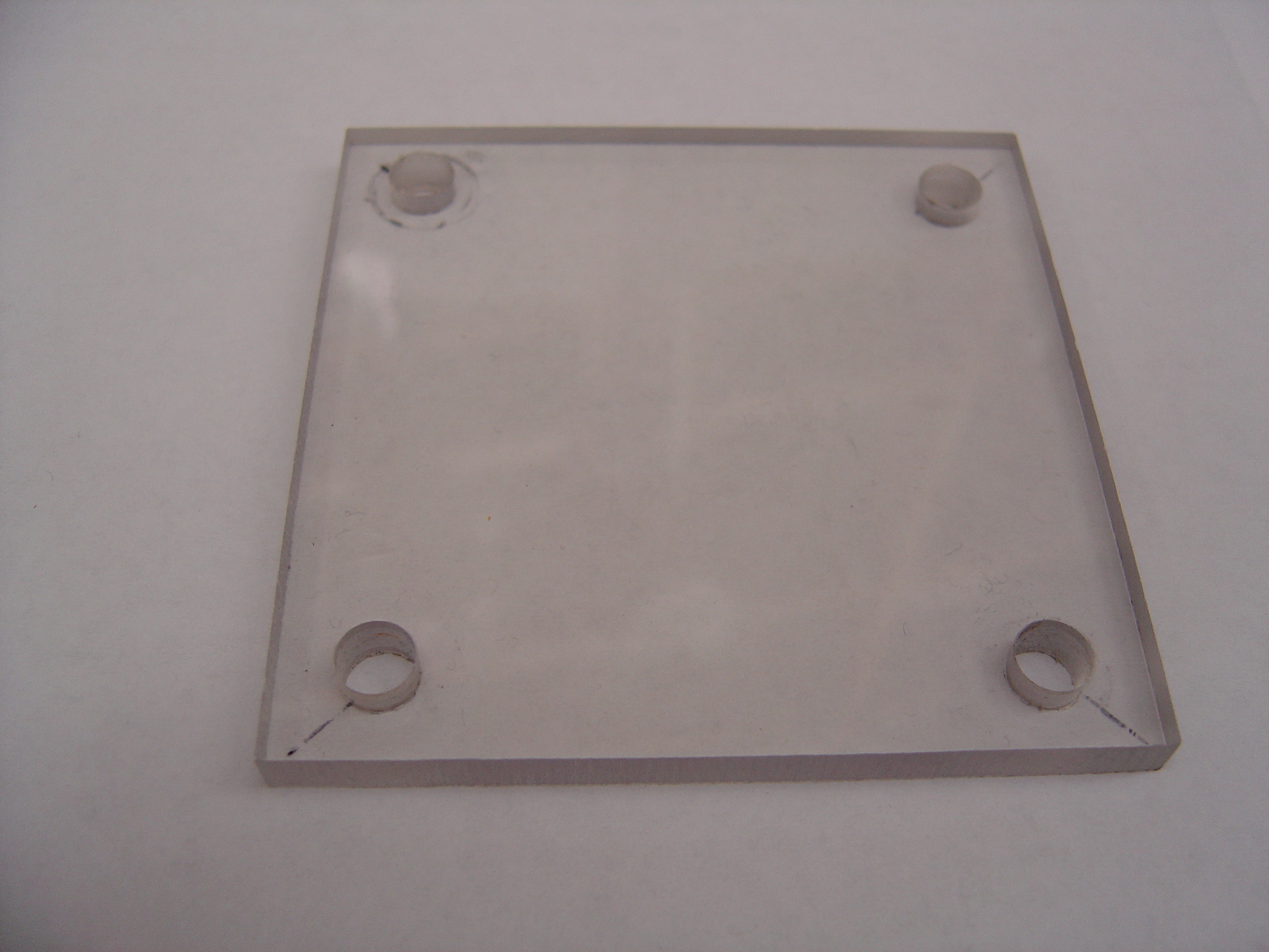
    • Cut polycarbonate sheet into 4 equal 3" x 3" pieces
    • Drill four 3/8" holes through each piece, 1 per corner, indented 5mm from both sides

Endplates.jpg

    • Cut polycarbonate tube into two equal 2" halves
    • Drill four 1/4" holes through each half in configuration shown

Drilled tube.jpg

    • Tap each hole with 1/4" -28 spiral tap
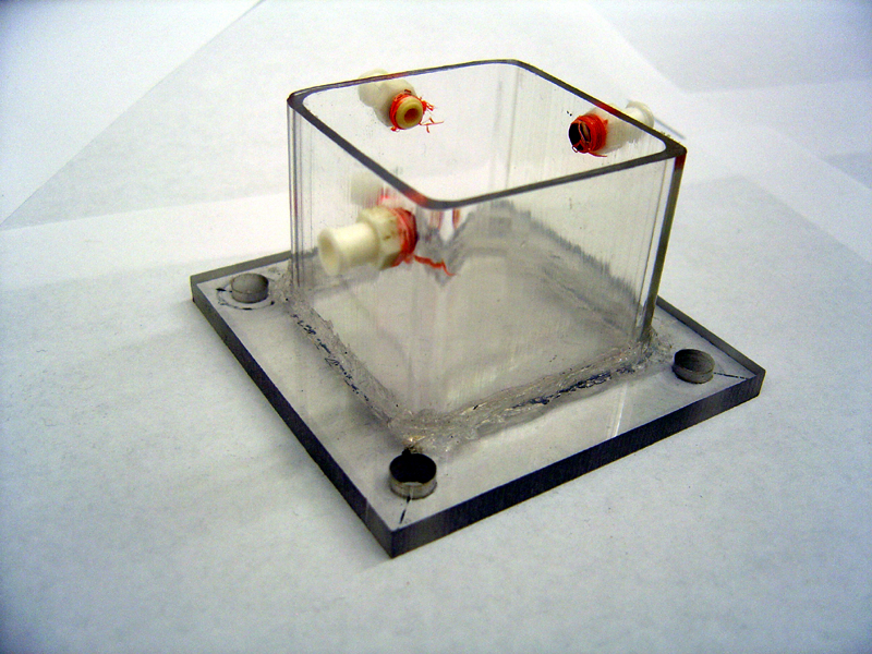
  1. Glue Chambers (repeat for each half)
    • Center tube on endplate by marking plate with 'X' from corner to corner
    • Squirt 2mm thick line of silicone on edge of tube (edge furthest from holes)
    • Press tube firmly against marked location on endplate
    • Quickly spread excess silicone along edge
    • Let stand 24h to harden

Glued half.jpg

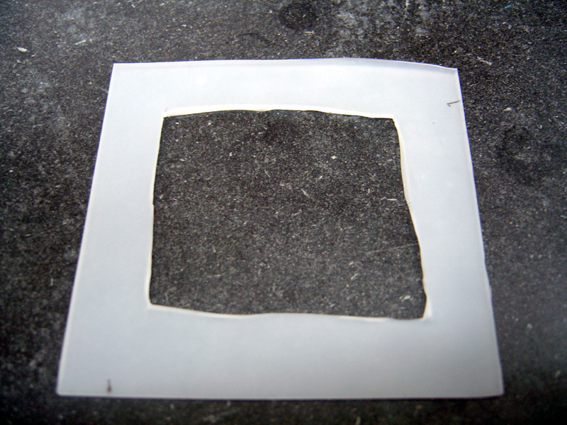
  1. Construct Gaskets
    • Cut silicone sheet into two equal 2.25" x 2.25" pieces
    • Cut out centered inner squares in each piece, 1.75" x 1.75"
    • Using inner squares, cut two 'O' rings, inner diameter 1/4", outer diameter 1/2"

Gaskets.jpg

  1. Construct Electrodes

600px

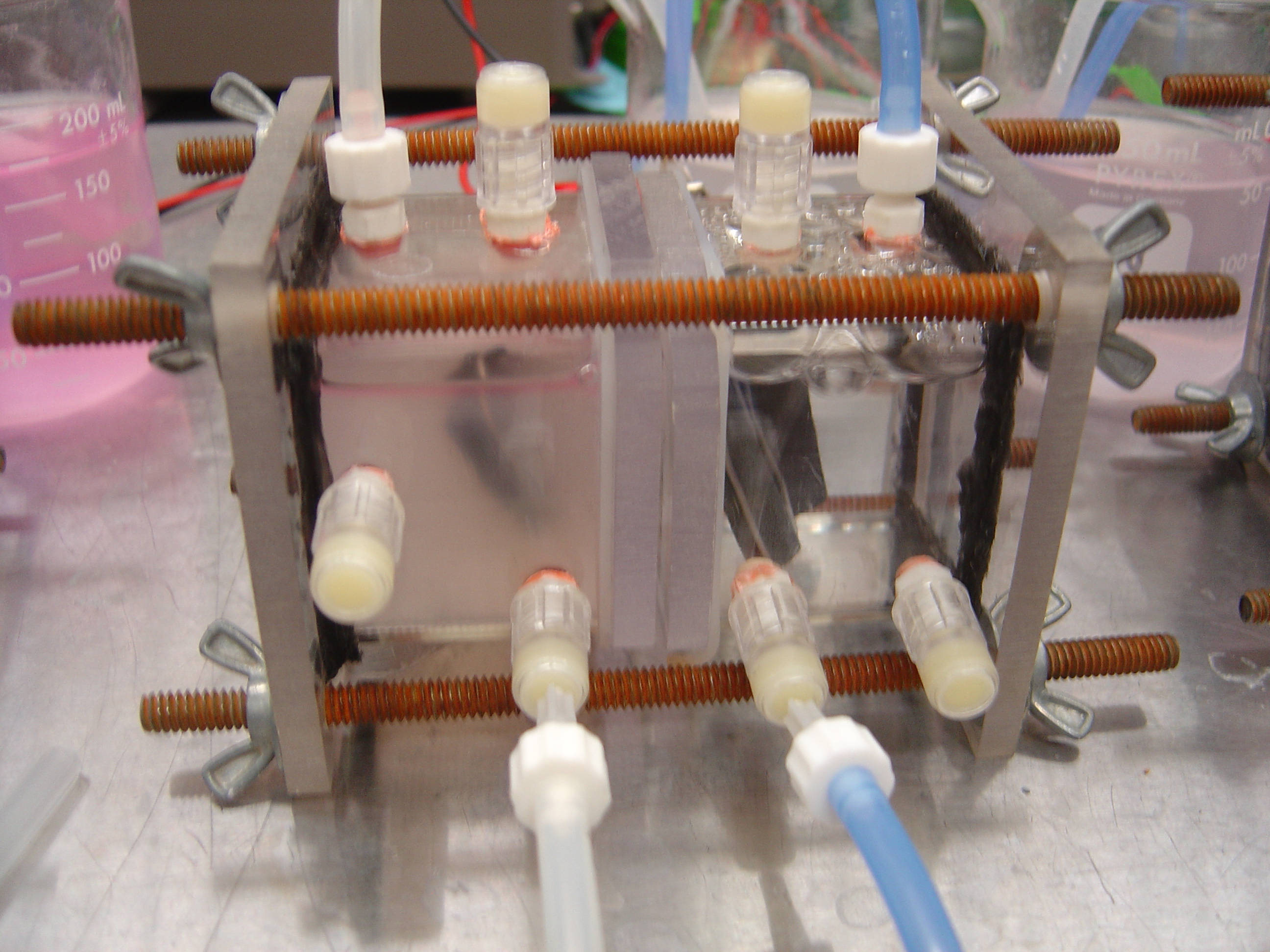
  1. Seal Injection Ports

Fin chamber.jpg


Setup of Digital Multimeter

Controlling the DMM with LabView™

Experiment Preparation

Begin 1 day prior to experiment

Assembling Chambers

Solutions Prep

Chamber media

  • 5.844 g/L 100mM NaCl
  • 15.1185 g/L 50mM PIPES (hydrogen)

7.0 pH

Phosphate buffer

  • 2.918 g/L Monosodium phosphate, monohydrate
  • 4.095 g/L Disodium phosphate, anhydrous
  • 5.844 g/L 100mM NaCl

7.0 pH

Gas Tubing Assembly

Growing Strains

Runtime

Begin 2 hours prior to experiment

Bacteria

Fuel Cells

Injections/Variables

Clean Up