Team:Harvard/Hardware/MFCProcedure
From 2008.igem.org
(Difference between revisions)
m |
m |
||
| (21 intermediate revisions not shown) | |||
| Line 65: | Line 65: | ||
===Constructing Fuel Cell Components=== | ===Constructing Fuel Cell Components=== | ||
| - | Materials (per fuel cell) | + | '''Materials (per fuel cell)''' |
* 4" Polycarbonate Square Tube, 2" Outer Diameter | * 4" Polycarbonate Square Tube, 2" Outer Diameter | ||
| Line 82: | Line 82: | ||
* 8 Luer Lock Injection Ports | * 8 Luer Lock Injection Ports | ||
| - | Procedure | + | '''Procedure''' |
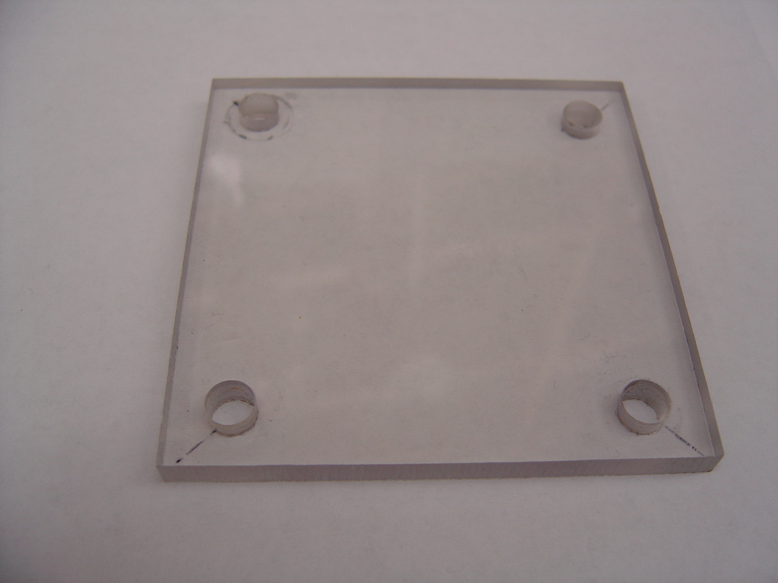
| - | + | 1) Mill Polycarbonate | |
| - | + | * Cut polycarbonate sheet into 4 equal 3" x 3" pieces | |
| - | + | * Drill four 3/8" holes through each piece, 1 per corner, indented 5mm from both sides | |
| + | * Drill a 1/2" hole in the center of each piece | ||
[[Image:endplates.jpg | 600px]] | [[Image:endplates.jpg | 600px]] | ||
| - | + | * Cut polycarbonate tube into two equal 2" halves | |
| - | + | * Drill four 1/4" holes through each half in configuration shown | |
[[Image:drilled_tube.jpg | 600px]] | [[Image:drilled_tube.jpg | 600px]] | ||
| - | + | * Tap each hole with 1/4" -28 spiral tap | |
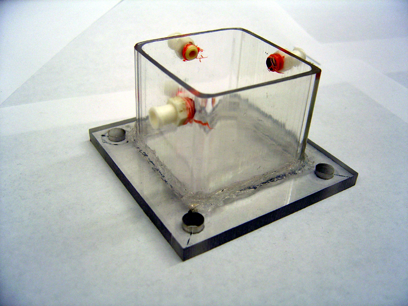
| - | + | 2) Glue Chambers (repeat for each half) | |
| - | + | * Center tube on endplate by marking plate with 'X' from corner to corner | |
| - | + | * Squirt 2mm thick line of silicone on edge of tube (edge furthest from holes) | |
| - | + | * Press tube firmly against marked location on endplate | |
| - | + | * Quickly spread excess silicone along edge | |
| - | + | * Let stand 24h to harden | |
[[Image:glued_half.jpg | 600px]] | [[Image:glued_half.jpg | 600px]] | ||
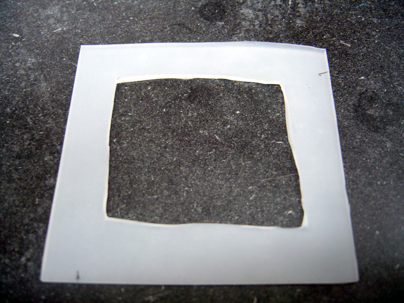
| - | + | 3) Construct Gaskets | |
| - | + | * Cut silicone sheet into two equal 2.25" x 2.25" pieces | |
| - | + | * Cut out centered inner squares in each piece, 1.75" x 1.75" | |
| - | + | * Using inner squares, cut two 'O' rings, inner diameter 1/4", outer diameter 1/2" | |
[[Image:gaskets.jpg | 600px]] | [[Image:gaskets.jpg | 600px]] | ||
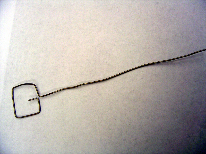
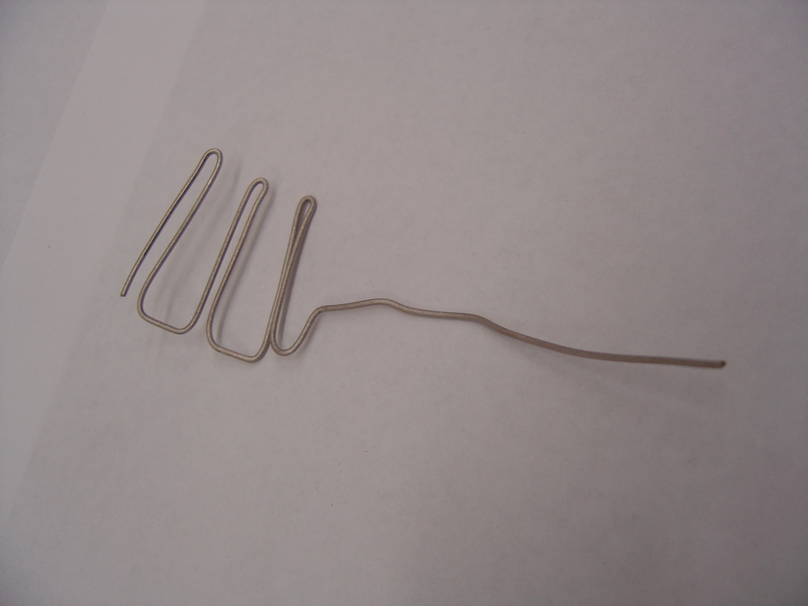
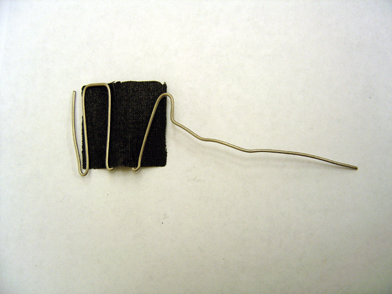
| - | + | 4) Construct Electrodes | |
| - | + | * Cut titanium wire into one 8" piece and one 16" piece | |
| - | + | * Using pliers, shape anode and cathode as shown | |
| - | [[Image: | + | '''Anode Frame'''<br> |
| - | + | [[Image:Anodeframe.jpg | 500px]]<br> | |
| - | + | '''Cathode Frame'''<br> | |
| - | [[Image: | + | [[Image:Cathodeframe.jpg | 500px]] |
| - | + | * Spear carbon felt with tip of anode titanium wire and wedge into frame | |
| - | + | * Weave platinum carbon cloth through cathode titanium wire | |
| - | + | '''Anode'''<br> | |
| + | [[Image:Anode_electrode.jpg | 500px]]<br> | ||
| + | '''Cathode'''<br> | ||
| + | [[Image:Cathode_electrode.jpg | 500px]] | ||
| + | |||
| + | 5) Seal Injection Ports | ||
| + | * Wrap threads of all eight Luer Lock screws with 1' of teflon tape in opposite direction of screwing | ||
| + | * Screw Luer Locks into all tapped holes in both chambers | ||
[[Image:fin_chamber.jpg | 600px]] | [[Image:fin_chamber.jpg | 600px]] | ||
| - | |||
===Setup of Measurement Device=== | ===Setup of Measurement Device=== | ||
| - | Materials | + | '''Materials''' |
* Keithley 2700 Digital Multimeter | * Keithley 2700 Digital Multimeter | ||
* Keithley 7700 Multiplexer | * Keithley 7700 Multiplexer | ||
| Line 130: | Line 137: | ||
* 470 Ohm resistors (one/fuel cell) | * 470 Ohm resistors (one/fuel cell) | ||
| - | Procedure | + | '''Procedure''' |
| - | + | 1) Wire Multiplexer | |
| - | + | * Open multiplexer, note channels | |
| - | + | * Cut two wire 18" wire leads per fuel cell | |
| - | + | * Strip ends, place one wire in each screw terminal, screw tight | |
| - | + | * Tape paired wires (two are attached to each channel) near non-attached ends and label | |
| - | + | * Clamp wire bundles near back of device with provided plastic latch clamps | |
| - | + | * Close Multiplexer and slide into 2700 DMM | |
| - | + | 2) Create Resistor Array | |
| - | + | * Connect resistors across middle of breadboard (one per fuel cell) | |
| - | + | * Connect leads from multiplexer across resistors (one pair across each resistor) | |
| Line 148: | Line 155: | ||
# Initialize Multimeter | # Initialize Multimeter | ||
#* Attach 2700 to COM1 port of desktop computer w/ LabVIEW™ | #* Attach 2700 to COM1 port of desktop computer w/ LabVIEW™ | ||
| - | #* Download our LabVIEW™ source code [[Media:MFCs. | + | #* Download our LabVIEW™ source code [[Media:MFCs.txt|MFCs.vi]] |
#* Open Program in LabVIEW™, adjust block diagram as necessary | #* Open Program in LabVIEW™, adjust block diagram as necessary | ||
| Line 157: | Line 164: | ||
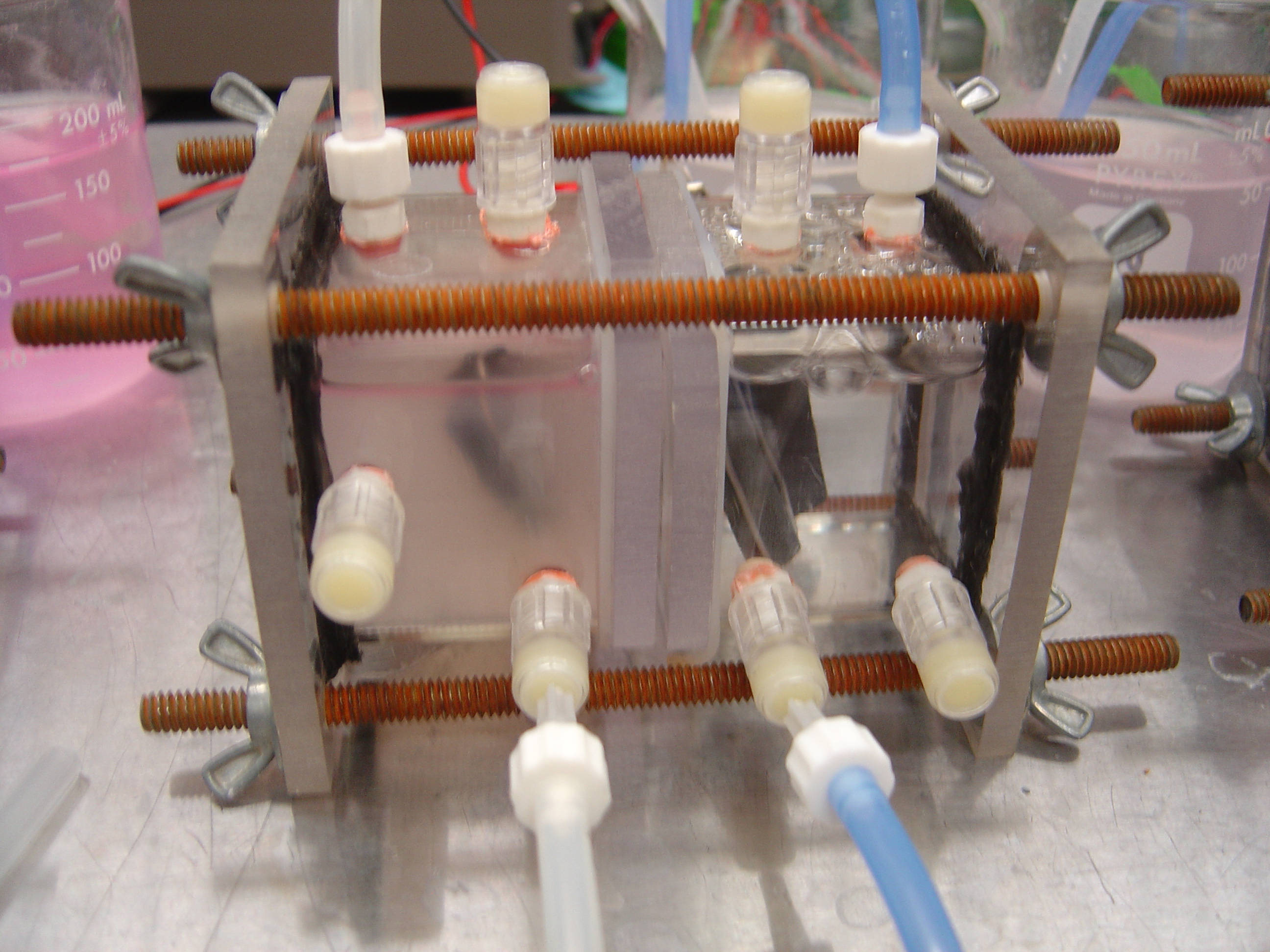
===Assembling Chambers=== | ===Assembling Chambers=== | ||
| - | Procedure | + | '''Procedure'''<br> |
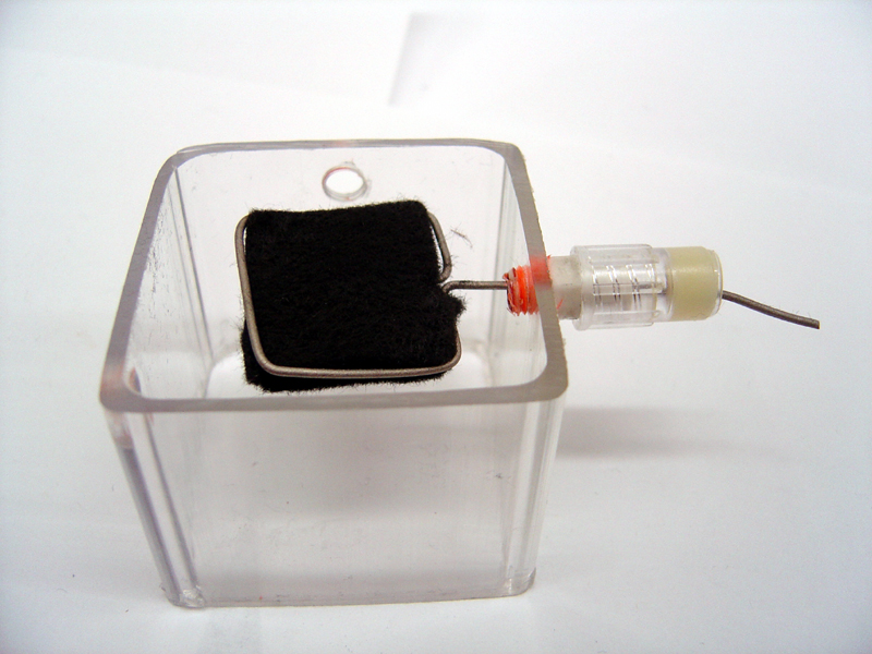
| - | + | 1) Prepare Electrodes | |
| - | + | * Attach Luer Lock injection ports to all chamber screws | |
| - | + | * Poke tip of electrodes through designated ports from the inside | |
[[Image:chamber_w_elec.jpg | 600px]] | [[Image:chamber_w_elec.jpg | 600px]] | ||
| - | + | <br> | |
| - | + | 2) Align Chambers | |
| - | + | * Lay one chamber on a flat surface | |
| - | + | * Place silicone square ring on top edge of tube | |
| - | + | * Place polycarbonate square on silicone | |
| - | + | * Place silicone 'O' ring around central pore | |
| - | + | * Place Nafion membrane on top of 'O' ring | |
| - | + | * Sandwich membrane between second 'O' ring | |
| - | + | * Align second polycarbonate square on top of 'O' ring | |
| - | + | * Center second silicone square ring on polycarbonate square | |
| - | + | * Set second chamber on top of silicone, ensuring ports facing same direction as first chamber | |
| - | + | <br> | |
| - | + | 3) Clamp Chambers | |
| - | + | * Move assembly into vice or clamp | |
| - | + | * Insert rods through holes in end plates and screw on wing nuts | |
| - | + | * Tighten evenly | |
| - | + | ||
===Solutions Prep=== | ===Solutions Prep=== | ||
| - | # Chamber media | + | # Chamber media (150ml / fuel cell) |
#* 5.844 g/L 100mM NaCl | #* 5.844 g/L 100mM NaCl | ||
#* 15.1185 g/L 50mM PIPES (hydrogen) | #* 15.1185 g/L 50mM PIPES (hydrogen) | ||
#* ''7.0 pH'' | #* ''7.0 pH'' | ||
| - | + | # Phosphate buffer (60ml / fuel cell) | |
| - | # Phosphate buffer | + | |
#* 2.918 g/L Monosodium phosphate, monohydrate | #* 2.918 g/L Monosodium phosphate, monohydrate | ||
#* 4.095 g/L Disodium phosphate, anhydrous | #* 4.095 g/L Disodium phosphate, anhydrous | ||
#* 5.844 g/L 100mM NaCl | #* 5.844 g/L 100mM NaCl | ||
#* ''7.0 pH'' | #* ''7.0 pH'' | ||
| + | # Resazurin solution | ||
| + | #* 0.489 g/L 0.8mM Resazurin | ||
| + | # Lactate Solution | ||
| + | #* 13.51 g/L Lactic acid | ||
| + | #* neutralize to pH 7 with NaOH | ||
===Gas Tubing Assembly=== | ===Gas Tubing Assembly=== | ||
| + | '''Materials''' | ||
| + | * 25' Silicone Soft Rubber Tubing, 3/32" ID, 7/32" OD, 1/16" Wall | ||
| + | * Tank of Compressed Nitrogen | ||
| + | * Gas Regulator | ||
| + | * Lab Supply of Air | ||
| + | * 4 Plastic Luer Lock Coupling Nylon, Male X Barb, for 3/32" Tube | ||
| + | * 4 Plastic Luer Lock Coupling Nylon, Female X Barb, for 3/32" Tube | ||
| + | * Plastic Luer Lock Coupling Nylon, T junctions, for 3/32" Tube | ||
| + | * Syringe needles - 27 gauge | ||
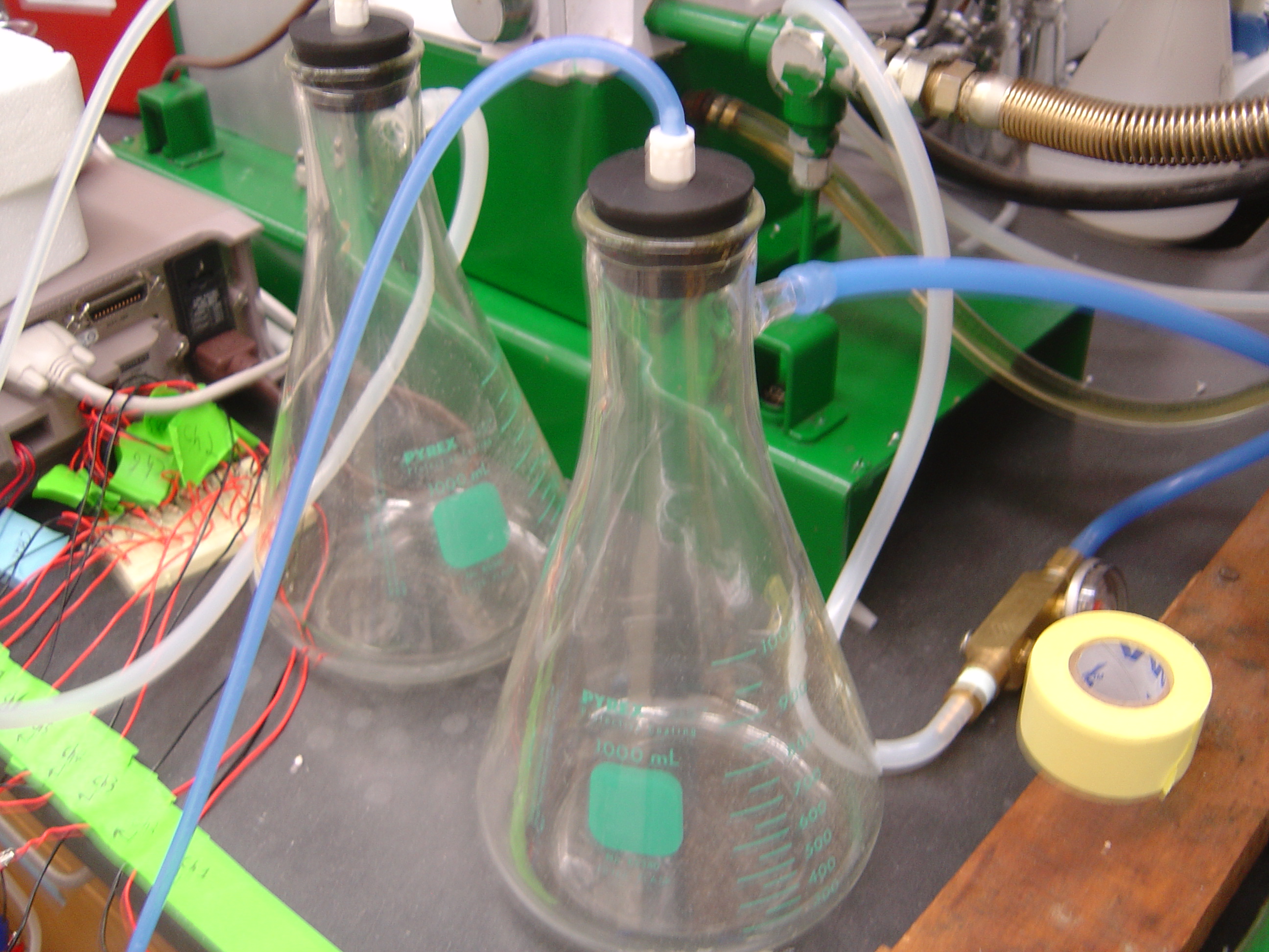
| + | * 2 Aspirator Flasks | ||
| + | * 2 Rubber Stoppers | ||
| + | |||
| + | '''Procedure''' | ||
| + | 1) Make Flow Regulators | ||
| + | * Insert nozzle of female Luer Lock into rubber stoppers (poke hole if necessary) | ||
| + | * Cap aspirator flasks with rubber stoppers | ||
| + | * Attach tubing from gas sources to each glass nozzle of aspirator flask | ||
| + | [[Image:flow_regs.jpg | 600px]] | ||
| + | |||
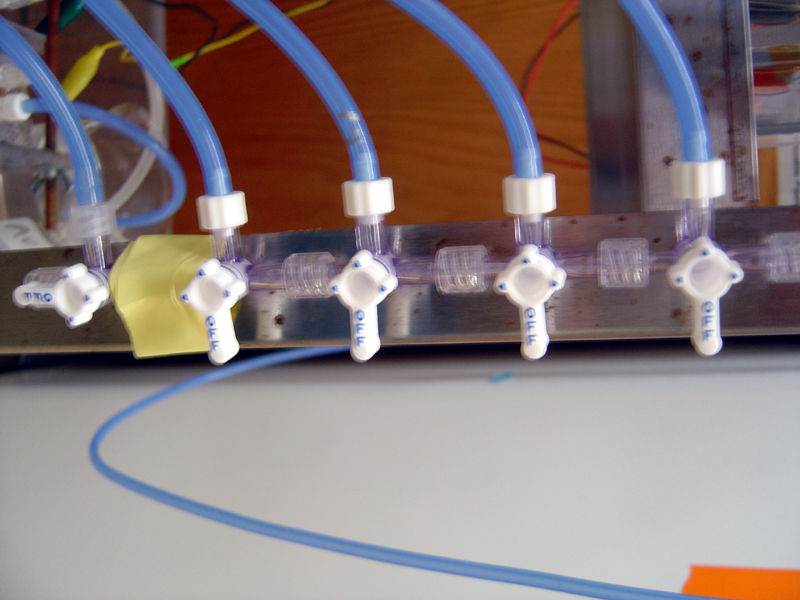
| + | 2) Make Manifolds | ||
| + | * Attach T-junction Luer Lock pieces into manifold (1 junction/ fuel cell ; 2 manifods total) | ||
| + | * Turn last juction such that off is facing end of manifold | ||
| + | * Attach tubing from stopper of flow regulators to beginning of each mainfold | ||
| + | [[Image:manifolds.jpg | 600px]] | ||
===Growing Strains=== | ===Growing Strains=== | ||
| + | |||
| + | Materials | ||
| + | |||
| + | * 150mL LB / strain | ||
| + | * 1000mL airating flask / strain | ||
| + | * Antibiotics (if desired strain must be selected for) | ||
| + | * Plate or Glycerol Stock with desired strain | ||
| + | |||
| + | Procedure | ||
| + | |||
| + | # Fill flasks with LB | ||
| + | # Add correct concentration of selection antibiotic | ||
| + | # Pick single colony from plate, add to flask | ||
| + | # Incubate overnight in shaker at 30C | ||
==Runtime== | ==Runtime== | ||
| Line 203: | Line 251: | ||
===Bacteria=== | ===Bacteria=== | ||
| + | |||
| + | Procedure | ||
| + | |||
| + | # Pipet the cells out of the flask and into 250mL centrifuge containers | ||
| + | # Make sure the containers are close in weight (within 0.5g of each other) | ||
| + | # For a culture more than 250mL split it into two containers | ||
| + | # Set the centrifuge temperature to 22-23C, spin speed to 5000RPM, and time to 15 min | ||
| + | # After first spin, drain each container of the LB, making sure to leave the bacteria pellet intact | ||
| + | # Resuspend pellet in 50mL of potassium buffer | ||
| + | # After bacteria are fully resuspended (no pellets at all), spin down again, 22-23C, 5000RPM, 15min. | ||
| + | # Pour potassium buffer out of container slowly. | ||
| + | # Resuspend pellet in 50mL of potassium buffer | ||
| + | # Spin down again, 22-23C, 5000RPM, 15min. | ||
| + | # Pour potassium buffer out of container slowly. | ||
| + | # Resuspend pellet in 4 mL of sodium pipes | ||
| + | # Check OD (100microliters in 15mL or 1:150 dilution) | ||
| + | # If OD is in linear range, calculate dilution for desired quantity of bacteria in 1mL (typically 10^8 cells /mL of chamber media) | ||
| + | # Repeat dilution if not in linear range (using different ratio) | ||
| + | # Inject 1mL of bacteria into each chamber (see below) | ||
===Fuel Cells=== | ===Fuel Cells=== | ||
| + | |||
| + | Procedure | ||
| + | |||
| + | # Pipet 75mL of NaPiPES solution into each side of fuel cells | ||
| + | # Inject 1mL of Resazurin solution into each side of chamber | ||
| + | # Using Luer Lock nozzles, connect tubing from top ports to beaker w/ distilled water | ||
| + | # Cut tubing to span distance from manifolds to each fuel cell (1 from nitrogen, 1 from air) | ||
| + | # Attach syringe needles to tubing via Luer Lock nozzles | ||
| + | # Using Luer Lock nozzles, connect tubing from manifolds | ||
| + | # Start gas flow | ||
| + | # Poke needles through bottom ports on fuel cells | ||
| + | |||
| + | ===Measurements=== | ||
| + | |||
| + | Procedure | ||
| + | |||
| + | # Turn on computer and digital multimeter | ||
| + | # Open LabVIEW program | ||
| + | # Click Run arrow to take resistance readings | ||
| + | # Connect fuel cells to resistor array via alligator clips | ||
| + | # Click "Begin Current Readings" Icon on instrument display | ||
===Injections/Variables=== | ===Injections/Variables=== | ||
| + | |||
| + | Procedure | ||
| + | |||
| + | # Once current readings reach equilibrium, inject bacteria into fuels cells using syringes | ||
| + | # Allow bacteria to consume any carbon sources left in their media (approximately 12 hours) | ||
| + | # Once current levels reach stable baseline, inject 1ml lactate solution | ||
| + | # Inject additional variables as desired | ||
==Clean Up== | ==Clean Up== | ||
| + | |||
| + | Procedure | ||
| + | |||
| + | # Drain chambers and soak in 70% ethanol | ||
| + | # Remove carbon felt from anodes and discard (save titanium) | ||
| + | # Scrub all parts in ethanol and distilled water successively | ||
| + | # Use pipe cleaners on ports and tubes | ||
| + | |||
| + | |||
| + | |||
|} | |} | ||
<br><br> | <br><br> | ||
Latest revision as of 04:10, 30 October 2008
|
|
 "
"

