Team:Alberta NINT/Project
From 2008.igem.org
m (header bar w/ links colour change) |
(→How to run a successful iGEM Team) |
||
| (27 intermediate revisions not shown) | |||
| Line 50: | Line 50: | ||
<div class='NINTBar'> | <div class='NINTBar'> | ||
| - | {| style="color:#FFFFFF;background-color:#000066;" cellpadding="3" cellspacing="1" border="1" bordercolor="#fff" width=" | + | {| style="color:#FFFFFF;background-color:#000066;" cellpadding="3" cellspacing="1" border="1" bordercolor="#fff" width="900px" align="center" |
| - | !align="center"|[[Team:Alberta_NINT|Home]] | + | !align="center"|[[Team:Alberta_NINT|<span title="Home">Home</span>]] |
| - | !align="center"|[[Team:Alberta_NINT/Team|The Team]] | + | !align="center"|[[Team:Alberta_NINT/Team|<span title="The Team">The Team</span>]] |
| - | !align="center"|[[Team:Alberta_NINT/Project|The Project]] | + | !align="center"|[[Team:Alberta_NINT/Project|<span title="Project Logi-col[i]">The Project</span>]] |
| - | !align="center"|[[Team:Alberta_NINT/Protocols|Lab Protocols]] | + | !align="center"|[[Team:Alberta_NINT/Protocols|<span title="Lab Protocols">Lab Protocols</span>]] |
| - | !align="center"|[[Team:Alberta_NINT/Parts|Bits and Pieces]] | + | !align="center"|[[Team:Alberta_NINT/Parts|<span title="Constructed Parts">Bits and Pieces</span>]] |
| - | !align="center"|[[Team:Alberta_NINT/Modeling|Modeling]] | + | !align="center"|[[Team:Alberta_NINT/Modeling|<span title="Modeling and Downloadable Materials">Modeling</span>]] |
| - | !align="center"|[[Team:Alberta_NINT/Notebook|Notebook]] | + | !align="center"|[[Team:Alberta_NINT/Notebook|<span title="Notebook">Notebook</span>]] |
|} | |} | ||
</div> | </div> | ||
<br> | <br> | ||
| - | [[Image:NINTiGEM_Header2.jpg|center| | + | [[Image:NINTiGEM_Header2.jpg|center|900px]]<br><br> |
== '''Manipulating RNA attenuator sequences to generate genetic logic circuits in ''E. coli''...''' == | == '''Manipulating RNA attenuator sequences to generate genetic logic circuits in ''E. coli''...''' == | ||
| Line 85: | Line 85: | ||
=== Terminators === | === Terminators === | ||
| - | [[image: | + | [[image:NINT_Draw_ProjectDetails_HisTerm2.jpg|300 px|frameless|right|Classic his terminator]] |
<p style ="padding: 30px; text-align:justify"> | <p style ="padding: 30px; text-align:justify"> | ||
| Line 91: | Line 91: | ||
<br><br></p> | <br><br></p> | ||
| - | [[image: | + | [[image:NINT_Draw_ProjectDetails_HisTermDisrupted2.jpg|300 px|frameless|right|Anti-sense disruption of terminator]] |
=== Anti-sense disruption of terminator/attenuators === | === Anti-sense disruption of terminator/attenuators === | ||
| Line 98: | Line 98: | ||
<br><br></p> | <br><br></p> | ||
| + | <br> | ||
| - | [[image: | + | [[image:NINT_Draw_ProjectDetails_TermAntiTerm2.jpg|frameless|right|300 px|Terminators and Anti-terminators]] |
=== Terminators and anti-terminators === | === Terminators and anti-terminators === | ||
| Line 105: | Line 106: | ||
<br>TA sequences can be preceded by competing sequences which preferentially form stem-loop-stem structures that are not followed immediately by U-rich terminating sequences. Such structures are called anti-terminators. If the stability of the anti-terminator structure is greater than that of the following terminator structure, it will be preferentially formed and prevent attenuation of the RNA transcript. In the image (right) a terminator (T) structure is out-competed by an anti-terminator structure (AT). The colors overlapping the sequence correlate to the colors in the cartoon of the structures. | <br>TA sequences can be preceded by competing sequences which preferentially form stem-loop-stem structures that are not followed immediately by U-rich terminating sequences. Such structures are called anti-terminators. If the stability of the anti-terminator structure is greater than that of the following terminator structure, it will be preferentially formed and prevent attenuation of the RNA transcript. In the image (right) a terminator (T) structure is out-competed by an anti-terminator structure (AT). The colors overlapping the sequence correlate to the colors in the cartoon of the structures. | ||
<br><br></p> | <br><br></p> | ||
| + | |||
| + | <br><br><br><br><br><br><br> | ||
=== TA Logic gates === | === TA Logic gates === | ||
| - | <p style ="padding: | + | <p style ="padding: 30px; text-align:justify"> |
<br>The classic terminator/attenuator (TA) structure component is a THRU gate. If it receives no input anti-sense RNA, no output transcript is produced. When it is disrupted by the appropriate anti-sense input, transcription proceeds, producing an output signal. By contrast, the single anti-terminator (AT) structure, as shown above, is a classic NOT gate. With no input, the AT forms in preference to the T structure and transcription can proceed, producing the output signal. Input anti-sense RNA disrupts the AT structure in favor of the formation of the T structure, prematurely attenuating transcription and stopping output production. | <br>The classic terminator/attenuator (TA) structure component is a THRU gate. If it receives no input anti-sense RNA, no output transcript is produced. When it is disrupted by the appropriate anti-sense input, transcription proceeds, producing an output signal. By contrast, the single anti-terminator (AT) structure, as shown above, is a classic NOT gate. With no input, the AT forms in preference to the T structure and transcription can proceed, producing the output signal. Input anti-sense RNA disrupts the AT structure in favor of the formation of the T structure, prematurely attenuating transcription and stopping output production. | ||
</p> | </p> | ||
| - | [[image: | + | [[image:NINT_Draw_ProjectDetails_ANDGate2.jpg|frameless|right|400 px|AND gate]] |
<p style ="padding: 50px; text-align:justify"> | <p style ="padding: 50px; text-align:justify"> | ||
Binary logic functions can also be encoded in T/AasL as illustrated with the AND gate (right). In this case a single RNA transcript contains two T structures. In order to produce a complete transcript (and corresponding output), anti-sense signals disrupting each of the T structures must be input. This gate is off with all other input combinations. | Binary logic functions can also be encoded in T/AasL as illustrated with the AND gate (right). In this case a single RNA transcript contains two T structures. In order to produce a complete transcript (and corresponding output), anti-sense signals disrupting each of the T structures must be input. This gate is off with all other input combinations. | ||
<br></p> | <br></p> | ||
| - | [[image: | + | [[image:NINT_Draw_ProjectDetails_ORGate1_2.jpg|frameless|right|400 px|OR gate (part one)]] |
<p style ="padding: 50px; text-align:justify"> | <p style ="padding: 50px; text-align:justify"> | ||
The construction of an OR gate requires the introduction of an additional component, the anti-anti-terminator (AAT). This structure is similar to both terminator and anti-terminator structures in its stem-loop-stem secondary folding. However, it lies 5' to the anti-terminator and prevents the formation of the AT structure through greater thermodynamic stability. If an AAT - AT - T scheme is present on a transcript and the relative stabilities are correctly adjusted (stability of AAT > AT > T) then an OR gate can be formed. The first image (right) shows the OR gate operation with a single input at the AAT. This causes the disruption of the AAT, leading to the formation of the AT over the formation of the T. Thus, transcription is able to complete. | The construction of an OR gate requires the introduction of an additional component, the anti-anti-terminator (AAT). This structure is similar to both terminator and anti-terminator structures in its stem-loop-stem secondary folding. However, it lies 5' to the anti-terminator and prevents the formation of the AT structure through greater thermodynamic stability. If an AAT - AT - T scheme is present on a transcript and the relative stabilities are correctly adjusted (stability of AAT > AT > T) then an OR gate can be formed. The first image (right) shows the OR gate operation with a single input at the AAT. This causes the disruption of the AAT, leading to the formation of the AT over the formation of the T. Thus, transcription is able to complete. | ||
<br></p> | <br></p> | ||
| - | [[image: | + | [[image:NINT_Draw_ProjectDetails_ORGate2_2.jpg|frameless|right|400 px|OR gate (part two)]] |
<p style ="padding: 50px; text-align:justify"> | <p style ="padding: 50px; text-align:justify"> | ||
The second image (right) shows the OR gate operation with a single input at the T. In this case, the presence of the AAT structure is not disrupted, but transcription is completed regardless, due to the direction disruption of the attenuating T structure. With no signal at either component, the top structure in each image is formed (an AAT plus a T) and transcription is attenuated. With both signals present, the AT forms and transcription is completed. The completely describes the behavior of the classic OR gate. | The second image (right) shows the OR gate operation with a single input at the T. In this case, the presence of the AAT structure is not disrupted, but transcription is completed regardless, due to the direction disruption of the attenuating T structure. With no signal at either component, the top structure in each image is formed (an AAT plus a T) and transcription is attenuated. With both signals present, the AT forms and transcription is completed. The completely describes the behavior of the classic OR gate. | ||
<br><br></p> | <br><br></p> | ||
| + | |||
| + | <br> | ||
=== TAasL gate design considerations === | === TAasL gate design considerations === | ||
| - | + | Please see the following document for detailed plasmid design and construction considerations. | |
| - | + | [[Media:NINT_PlasmidDesignAndConstruction.pdf|Plasmid Design and Construction]] | |
| - | + | <br> | |
| - | + | ||
== Results == | == Results == | ||
| - | + | === Terminator efficiency === | |
| + | [[image:NINT_ResultsTE.jpg|frameless|center|800 px]] | ||
| + | We transformed output test harnesses containing the various T/AasL gates into XL1-Blue cells and performed a standard LacZ assay (see Protocols). This graph shows how well the various gates perform their terminator or anti-terminator function in the absence of any input. The y-axis is shown in Miller units (the standard for such assays). | ||
| + | |||
| + | The "2021" gate is a TRUE gate (always ON) and this represents the maximum LacZ activity we can expect to see in our assay. 2031 is a THRU gate (echoes input) based on the natural his terminator and should be OFF without input. It's LacZ activity is reduced from 2021 as expected. The next gates (2041 - 2101) are various attempts to design an improved synthetic terminator. Some of them (2041, 2051) show slightly lower activity than 2031, others (2051, 2071, 2091, 2101)are about the same as 2031, while 2081 seems not to function at all. 2091 and 2101 are the same gate but 2101 contains a "pause" sequence which was hypothesized to improve the gate function by allowing time for the terminator to form. There is no difference between these two. | ||
| + | |||
| + | The last two gate (2111, 2121) are anti-terminators which should be ON in the absence of input. 2121 also conatins a pause sequence. Both of these gates show the same amount of activity as 2021 (always ON) as expected and the pause does not improve the gate function. | ||
| + | |||
| + | === Terminator Stability vs Efficiency === | ||
| + | |||
| + | [[image:NINT_ResultsTEvsStability.jpg|frameless|center|800 px]] | ||
| + | |||
| + | This graph compares the thermodynamic stability (kCal/mole from RNAStructure 4.5) to the termination efficiency. If there were a direct correlation between these two, we might expect to see a relationship like that shown by the drawn-in line. However, there is clearly no correlation observed between these two data. | ||
| + | |||
| + | === Activation of T/AasL gates by input anti-sense RNA === | ||
| + | |||
| + | [[image:NINT_ResultsAnti-SenseActivation.jpg|frameless|center|800 px]] | ||
| + | |||
| + | Finally, we co-transformed input and output test harnesses into XL1-Blue cells to measure how well the anti-sense input (induced by arabinose) activates the gate in the output test harness plasmid to produce LacZ activity. In order to compensate for variability in any population of transformed cells, we compared the activation of the gate by its "correct" input (e.g. for BBa_K102031 that is BBa_K102034 containing the BBa_K102951 input)) to the activation a "null" input (BBa_K102011 containing the BBa_K102950 input). This induction ratio is shown on the graph. | ||
| + | |||
| + | Unfortunately, none of the inputs seemed to activate their target gates more than the null input. This could have several explanations: | ||
| + | # Perhaps the gates are too stable and can't be disrupted by the inputs. | ||
| + | # Perhaps the anti-sense inputs have a very short half-life (due to their size or structure) and are unable to reach the gate. | ||
| + | # Perhaps there is not enough anti-sense input to be effective because it is on a low copy (1-5/cell) plasmid. | ||
| + | # Perhaps the gate/input RNA duplex is rapidly degraded before LacZ production can occur. | ||
| + | # Perhaps the arabinose (used to induce input anti-sense expression) causes an offsetting reduction in the PLac-inducible output plasmid. We have some evidence that arabinose does indeed cause this. | ||
| + | # Perhaps the effect is small and can't be seen against background "noise" of the system. | ||
| + | # Perhaps the hammerhead ribozymes flanking the input RNA are not working and the anti-sense signal cannot access the gate to activate it. | ||
| + | |||
| + | All of these potential explanations also suggest future experiments we plan to carry out, in order to determine whether this system can be engineered. | ||
== References == | == References == | ||
| Line 206: | Line 239: | ||
Otsuka, Y., and T. Yonesaki. 2005. A Novel Endoribonuclease, RNase LS, in Escherichia coli. Genetics 169:13-20. | Otsuka, Y., and T. Yonesaki. 2005. A Novel Endoribonuclease, RNase LS, in Escherichia coli. Genetics 169:13-20. | ||
| - | |||
| - | |||
| - | |||
=== Hammerhead Ribozymes === | === Hammerhead Ribozymes === | ||
| Line 215: | Line 245: | ||
Scott, W. G. 2007. Morphing the minimal and full-length hammerhead ribozymes: implications for the cleavage mechanism. Biol Chem 388:727-35. | Scott, W. G. 2007. Morphing the minimal and full-length hammerhead ribozymes: implications for the cleavage mechanism. Biol Chem 388:727-35. | ||
| + | |||
| + | Taira, K., K. Nakagawa, S. Nishikawa, and K. Furukawa. 1991. Construction of a novel RNA-transcript- | ||
| + | trimming plasmid which can be used both in vitro in place of run-off and (G)-free transcriptions and in vivo as multi-sequences transcription vectors. Nucleic Acids Res 19:5125-30. | ||
| + | |||
| + | |||
| + | === How to run a successful iGEM Team === | ||
| + | [[Media:Running_a_successful_iGEM_Team_Final.pdf|Running a Successful iGEM Team PDF file]] | ||
| + | <br> | ||
Latest revision as of 16:44, 30 March 2009
| Home | The Team | The Project | Lab Protocols | Bits and Pieces | Modeling | Notebook |
|---|
Contents |
Manipulating RNA attenuator sequences to generate genetic logic circuits in E. coli...
Terminator/Attenuator anti-sense Logic (T/AasL)
The integrated circuit was a major milestone of modern technology that facilitated the entry of society into the information age. Electrical circuits that once occupied an entire room are now able to be placed on a single micro-chip the size of a postage stamp. The implementation of Boolean logic (AND, OR, NOT, etc.) using integrated electronic circuits forms the basis for modern day computers.
When compared to electronics, similar levels of integration have yet to be realized in biological systems. While electronic devices are inherently connectible due to their common currency (flow of electrons), biological circuits lack similar connectivity. This poses a significant challenge to the development of truly programmable biosystems. Solving this challenge should open the door for development of biological devices just as integrated circuits led to an explosion of electronic devices.
The Logi-col[i] project hopes to overcome this challenge by constructing connectible, extensible biological circuits based on antisense RNA regulation of transcriptional attenuation. Transcriptional attenuation is a common biological mechanism for controlling transcriptional activity. As RNA strands are produced by RNA polymerase transcription of a DNA template, they often form secondary “stem-loop” structures due to base-pair complementarity of inverted repeat sequences. Inverted repeat sequences are short sequences in the transcript that are repeated at a later position in reverse order. These repeat sequences cause the RNA strand to fold back on itself due to base-pairing between complementary A-U and C-G nucleotide pairs in the different repeat regions. A terminator is formed at the end of an RNA transcript when such a simple stem-loop is followed by a “UUUUUUU” sequence that causes the severing of the nascent RNA strand and the dislocation of the RNA polymerase from the DNA template strand. An attenuator is a terminator structure, like the one described above, however found near the start of a transcript and has the ability to prematurely truncate the transcript.
We hypothesize that transcriptional attenuation can be modulated by the action of an anti-sense RNA strand disrupting the normal base-pairing in the attenuator stem-loop structure. As a result of this disruption, the RNA polymerase can continue transcription past the attenuator sequence. Using software called RNAstructure4.5, our team hopes to be able to rationally design functional attenuators and corresponding input anti-sense RNA sequences. In this way, we hope to provide a means for connecting series of circuits by using the output RNA strand of one circuit to regulate the transcription of a second circuit. We hope to combine simple attenuators into more complex structures that act as biological equivalents to electronic Boolean logic gates (AND, OR, XOR, etc.)
Thus, our scheme will be connectible because the output from one component (an RNA transcript) will be able to serve as the input to another component (the next TA gate). In addition, the scheme should provide for extensibility as it should be possible to rationally design a fairly large number of TA gates and anti-sense input/output signals with minimum cross-talk.
In regards to the final output, a LacZ coding region will be expressed to provide evidence of the functionality of the logic circuits. We hope to connect these basic logic gates into even more complex circuits such as half-adders or full-adders. This important step in the design of complex logic in biological circuits has eluded researchers for a number of years, but we believe our approach to have great potential for success. Potential applications for logical circuitry in organisms include almost any sensory, patterning or information processing scenario. Simple sensory circuits could potentially be combined to signal particular mixtures of molecules. Medical microbots could process complex chemical signals inside patient tissues and autonomously make therapeutic decisions based on their programming. Synthetic tissue could make patterning decisions to form biological shapes never seen in nature. Trying to describe the potential applications of programming behavior into living organisms is as difficult as describing the computer, cell phone or HDTV to a society which has just invented the lightbulb. Although we may be able to scratch the surface of the potential, it is certain that many unforeseen inventions will be generated in the future.
Project Details
Terminators
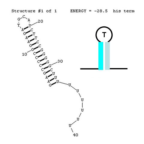
A classic terminator found at the 3' end of an RNA transcript consists of a "stem" structure of length ~10 to 30 nucleotides followed by a "loop" of 4-6 nucleotides, then several complementary nucleotides forming the corresponding 3' portion of the stem. Finally, a weakly-hybridizing sequence of about 9 nucleotides (mainly U's or A's) forms the portion that permits the nascent transcript to dissociate from the template DNA strand. The termination efficiency (TE) of this structure is determined by many complex factors, including its thermodynamic stability. For this structure (see right) this free energy is calculated by RNAStructure as -28.5 Kcal/mole. The inset image is a cartoon representation of the terminator. Similar images will be used throughout this description.
Anti-sense disruption of terminator/attenuators
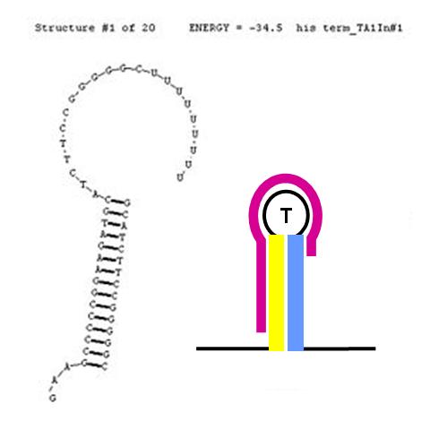
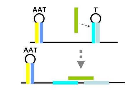
The formation of terminator/attenuator (T/A) stem-loop-stem hairpin structures can be disrupted using a second (anti-sense) RNA input sequence. If the hybrid double-stranded RNA sequence formed by the RNA transcript and the anti-sense RNA input has greater stability (lower free energy) than the original hairpin T/A structure, its formation will be preferred over the T/A, permitting RNA transcription to proceed past the T/A sequence. In the image (right), the input anti-sense sequence includes the entire 5' portion of the stem and the first three nucleotides in the loop. This is sufficient to confer an approximate 6 Kcal/mol stability advantage over the original TA secondary structure. This should cause this structure to be highly favoured thermodynamically.
Terminators and anti-terminators
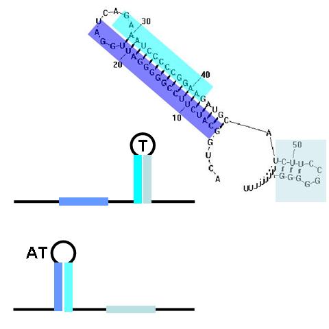
TA sequences can be preceded by competing sequences which preferentially form stem-loop-stem structures that are not followed immediately by U-rich terminating sequences. Such structures are called anti-terminators. If the stability of the anti-terminator structure is greater than that of the following terminator structure, it will be preferentially formed and prevent attenuation of the RNA transcript. In the image (right) a terminator (T) structure is out-competed by an anti-terminator structure (AT). The colors overlapping the sequence correlate to the colors in the cartoon of the structures.
TA Logic gates
The classic terminator/attenuator (TA) structure component is a THRU gate. If it receives no input anti-sense RNA, no output transcript is produced. When it is disrupted by the appropriate anti-sense input, transcription proceeds, producing an output signal. By contrast, the single anti-terminator (AT) structure, as shown above, is a classic NOT gate. With no input, the AT forms in preference to the T structure and transcription can proceed, producing the output signal. Input anti-sense RNA disrupts the AT structure in favor of the formation of the T structure, prematurely attenuating transcription and stopping output production.
Binary logic functions can also be encoded in T/AasL as illustrated with the AND gate (right). In this case a single RNA transcript contains two T structures. In order to produce a complete transcript (and corresponding output), anti-sense signals disrupting each of the T structures must be input. This gate is off with all other input combinations.
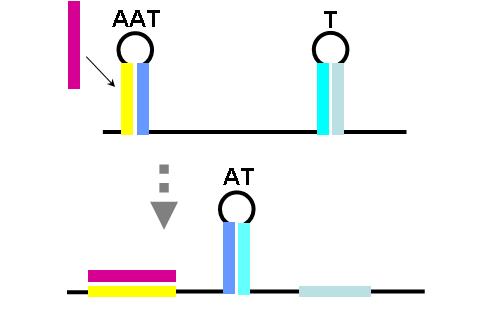
The construction of an OR gate requires the introduction of an additional component, the anti-anti-terminator (AAT). This structure is similar to both terminator and anti-terminator structures in its stem-loop-stem secondary folding. However, it lies 5' to the anti-terminator and prevents the formation of the AT structure through greater thermodynamic stability. If an AAT - AT - T scheme is present on a transcript and the relative stabilities are correctly adjusted (stability of AAT > AT > T) then an OR gate can be formed. The first image (right) shows the OR gate operation with a single input at the AAT. This causes the disruption of the AAT, leading to the formation of the AT over the formation of the T. Thus, transcription is able to complete.
The second image (right) shows the OR gate operation with a single input at the T. In this case, the presence of the AAT structure is not disrupted, but transcription is completed regardless, due to the direction disruption of the attenuating T structure. With no signal at either component, the top structure in each image is formed (an AAT plus a T) and transcription is attenuated. With both signals present, the AT forms and transcription is completed. The completely describes the behavior of the classic OR gate.
TAasL gate design considerations
Please see the following document for detailed plasmid design and construction considerations.
Plasmid Design and Construction
Results
Terminator efficiency
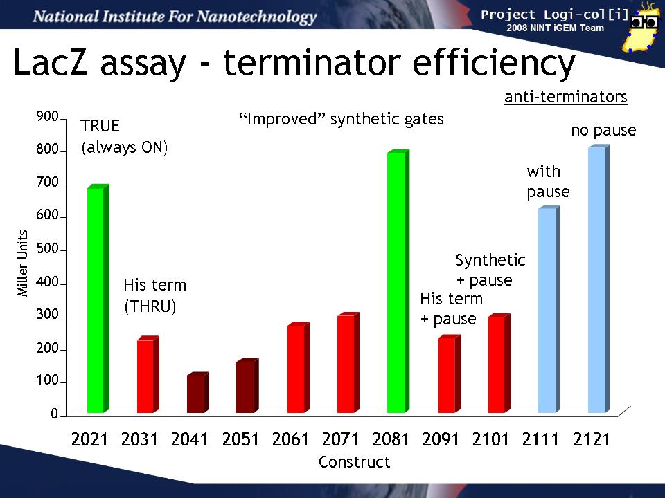
We transformed output test harnesses containing the various T/AasL gates into XL1-Blue cells and performed a standard LacZ assay (see Protocols). This graph shows how well the various gates perform their terminator or anti-terminator function in the absence of any input. The y-axis is shown in Miller units (the standard for such assays).
The "2021" gate is a TRUE gate (always ON) and this represents the maximum LacZ activity we can expect to see in our assay. 2031 is a THRU gate (echoes input) based on the natural his terminator and should be OFF without input. It's LacZ activity is reduced from 2021 as expected. The next gates (2041 - 2101) are various attempts to design an improved synthetic terminator. Some of them (2041, 2051) show slightly lower activity than 2031, others (2051, 2071, 2091, 2101)are about the same as 2031, while 2081 seems not to function at all. 2091 and 2101 are the same gate but 2101 contains a "pause" sequence which was hypothesized to improve the gate function by allowing time for the terminator to form. There is no difference between these two.
The last two gate (2111, 2121) are anti-terminators which should be ON in the absence of input. 2121 also conatins a pause sequence. Both of these gates show the same amount of activity as 2021 (always ON) as expected and the pause does not improve the gate function.
Terminator Stability vs Efficiency
This graph compares the thermodynamic stability (kCal/mole from RNAStructure 4.5) to the termination efficiency. If there were a direct correlation between these two, we might expect to see a relationship like that shown by the drawn-in line. However, there is clearly no correlation observed between these two data.
Activation of T/AasL gates by input anti-sense RNA
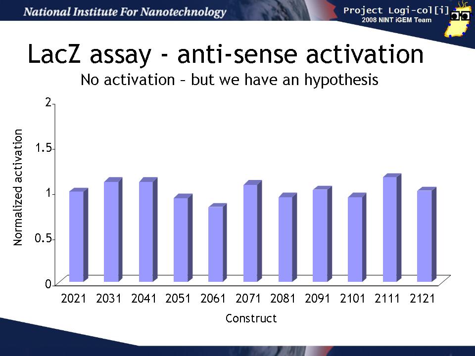
Finally, we co-transformed input and output test harnesses into XL1-Blue cells to measure how well the anti-sense input (induced by arabinose) activates the gate in the output test harness plasmid to produce LacZ activity. In order to compensate for variability in any population of transformed cells, we compared the activation of the gate by its "correct" input (e.g. for BBa_K102031 that is BBa_K102034 containing the BBa_K102951 input)) to the activation a "null" input (BBa_K102011 containing the BBa_K102950 input). This induction ratio is shown on the graph.
Unfortunately, none of the inputs seemed to activate their target gates more than the null input. This could have several explanations:
- Perhaps the gates are too stable and can't be disrupted by the inputs.
- Perhaps the anti-sense inputs have a very short half-life (due to their size or structure) and are unable to reach the gate.
- Perhaps there is not enough anti-sense input to be effective because it is on a low copy (1-5/cell) plasmid.
- Perhaps the gate/input RNA duplex is rapidly degraded before LacZ production can occur.
- Perhaps the arabinose (used to induce input anti-sense expression) causes an offsetting reduction in the PLac-inducible output plasmid. We have some evidence that arabinose does indeed cause this.
- Perhaps the effect is small and can't be seen against background "noise" of the system.
- Perhaps the hammerhead ribozymes flanking the input RNA are not working and the anti-sense signal cannot access the gate to activate it.
All of these potential explanations also suggest future experiments we plan to carry out, in order to determine whether this system can be engineered.
References
General Synthetic Biology
Andrianantoandro, E., S. Basu, D. K. Karig, and R. Weiss. 2006. Synthetic biology: new engineering rules for an emerging discipline. Mol Syst Biol 2:2006 0028.
Drubin, D. A., J. C. Way, and P. A. Silver. 2007. Designing biological systems. Genes Dev 21:242-54.
Endy, D. 2005. Foundations for engineering biology. Nature 438:449-453.
Genetic Logic
Anderson, J. C., C. A. Voigt, and A. P. Arkin. 2007. Environmental signal integration by a modular AND gate. Mol Syst Biol 3:133.
Bayer, T. S., and C. D. Smolke. 2005. Programmable ligand-controlled riboregulators of eukaryotic gene expression. Nat Biotech 23:337-343.
Gallivan, J. P. 2007. Toward reprogramming bacteria with small molecules and RNA. Current Opinion in Chemical Biology 11:612-619.
Grundy, F. J., and T. M. Henkin. 2006. From ribosome to riboswitch: control of gene expression in bacteria by RNA structural rearrangements. Crit Rev Biochem Mol Biol 41:329-38.
Isaacs, F. J., D. J. Dwyer, C. Ding, D. D. Pervouchine, C. R. Cantor and J. J. Collins. 2004. Engineered riboregulators enable post-transcriptional control of gene expression. Nat. Biotech 22:841-847.
Isaacs, F. J., D. J. Dwyer, and J. J. Collins. 2006. RNA synthetic biology. Nat Biotech 24:545-554.
Lynch, S. A., S. K. Desai, H. K. Sajja, and J. P. Gallivan. 2007. A high-throughput screen for synthetic riboswitches reveals mechanistic insights into their function. Chem Biol 14:173-84.
Termination / Attenuation
Gollnick, P., and P. Babitzke. 2002. Transcription attenuation. Biochimica et Biophysica Acta (BBA) - Gene Structure and Expression 1577:240-250.
Henkin, T. M., and C. Yanofsky. 2002. Regulation by transcription attenuation in bacteria: how RNA provides instructions for transcription termination/antitermination decisions. BioEssays 24:700-707.
Larson, M. H., W. J. Greenleaf, R. Landick, and S. M. Block. 2008. Applied Force Reveals Mechanistic and Energetic Details of Transcription Termination. Cell 132:971-982.
Merino, E., and C. Yanofsky. 2005. Transcription attenuation: a highly conserved regulatory strategy used by bacteria. Trends in Genetics 21:260-264.
Antisense-RNA
Brantl, S. 2002. Antisense-RNA regulation and RNA interference. Biochimica et Biophysica Acta (BBA) - Gene Structure and Expression 1575:15-25.
Brantl, S. 2007. Regulatory mechanisms employed by cis-encoded antisense RNAs. Current Opinion in Microbiology 10:102-109.
Brantl, S., and E. G. Wagner. 2002. An antisense RNA-mediated transcriptional attenuation mechanism functions in Escherichia coli. J Bacteriol 184:2740-7.
Brantl, S., and E. G. H. Wagner. 2000. Antisense RNA-mediated transcriptional attenuation: an in vitro study of plasmid pT181. Molecular Microbiology 35:1469-1482.
Gottesman, S. 2004. THE SMALL RNA REGULATORS OF ESCHERICHIA COLI: Roles and Mechanisms. Annual Review of Microbiology 58:303-328.
Heidrich, N., and S. Brantl. 2003. Antisense-RNA Mediated Transcriptional Attenuation: Importance of a U-turn Loop Structure in the Target RNA of Plasmid pIP501 for Efficient Inhibition by the Antisense RNA. Journal of Molecular Biology 333:917-929.
Heidrich, N., and S. Brantl. 2007. Antisense RNA-mediated transcriptional attenuation in plasmid pIP501: the simultaneous interaction between two complementary loop pairs is required for efficient inhibition by the antisense RNA. Microbiology 153:420-427.
Majdalani, N., C. K. Vanderpool, and S. Gottesman. 2005. Bacterial Small RNA Regulators. Critical Reviews in Biochemistry and Molecular Biology 40:93 - 113.
Transcription Pausing
Herbert, K. M., A. La Porta, B. J. Wong, R. A. Mooney, K. C. Neuman, R. Landick, and S. M. Block. 2006. Sequence-resolved detection of pausing by single RNA polymerase molecules. Cell 125:1083-94.
RNA maturation and stability
Condon, C. 2007. Maturation and degradation of RNA in bacteria. Current Opinion in Microbiology 10:271-278.
Deutscher, M. P. 2006. Degradation of RNA in bacteria: comparison of mRNA and stable RNA. Nucleic Acids Res 34:659-66.
Hjalt, T.A.H. and E.J.H. Wagner. (1995). Bulged-out nucleotides protect an antisense RNA from RNase III cleavage. Nucleic Acids Res. 23:571-579
Mohanty, B. K., and S. R. Kushner. 2006. The majority of Escherichia coli mRNAs undergo post-transcriptional modification in exponentially growing cells. Nucleic Acids Res 34:5695-704.
Otsuka, Y., and T. Yonesaki. 2005. A Novel Endoribonuclease, RNase LS, in Escherichia coli. Genetics 169:13-20.
Hammerhead Ribozymes
De la Pena, M., S. Gago, and R. Flores. 2003. Peripheral regions of natural hammerhead ribozymes greatly increase their self-cleavage activity. Embo J 22:5561-70.
Scott, W. G. 2007. Morphing the minimal and full-length hammerhead ribozymes: implications for the cleavage mechanism. Biol Chem 388:727-35.
Taira, K., K. Nakagawa, S. Nishikawa, and K. Furukawa. 1991. Construction of a novel RNA-transcript- trimming plasmid which can be used both in vitro in place of run-off and (G)-free transcriptions and in vivo as multi-sequences transcription vectors. Nucleic Acids Res 19:5125-30.
How to run a successful iGEM Team
Running a Successful iGEM Team PDF file
 "
"

