Fuel Cell Development
Motivation
The broad goal of our project was to engineer S. Oneidensis to produce a detectable change in electric current in response to some environmental stimulus. In order to observe such a reaction, our first task was to design an environment capable of housing bacteria and measuring current production.
Solution - Microbial Fuel Cells
Background
To measure the electric current production in Shewanella oneidensis MR-1, we constructed microbial fuel cells (MFCs) to harvest the electricity produced. Traditional fuel cells convert chemical energy to electrical energy. MFCs are unique in that the fuel source used is microbially degradable organic matter (Lovley 2006). Such organic matter is a form of renewable energy and can come from materials in wastewater, sediments, or agricultural wastes (Cho et al. 2007). Compared to hydrogen- and methanol-driven fuel cells, MFCs are particular attractive due to their ease of operation and wide range of fuel sources available. They do not require expensive catalysts, high operating temperatures, nor explosive or toxic fuels (Lovley 2006). Indeed, we found the construction and operation of our microbial fuel cells to be relatively straightforward.
MFCs operate using principles similar to normal fuel cells. MFCs require an anode and a cathode separated by a semi-permeable membrane (permeable to protons) (Lovley 2006). The anode compartment is generally anaerobic and is the site of oxidation of organic matter (Lovley 2006); the cathode transfers electrons to the electron acceptor (Lovley 2006). MFCs take advantage of the natural metabolism of microorganisms that break down organic matter by intercepting the electrons that would be donated to naturally occurring electron acceptors. Instead, these electrons are transferred from the anode to the cathode, usually along metal wires to which current readings can be taken.
A figure of a microbial fuel cell is shown below (NB: this is not what we used in our experiments).
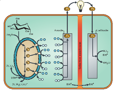
On the anode side, glucose is being metabolized by the microorganism to yield electrons which are transferred to the cathode side where oxygen is reduced to water (Lovley 2006).
Context
Shewanella oneidensis MR-1 is a suitable microorganism for a MFC. It is known to break down lactate (Bretschger et al. 2007), and in anaerobic conditions, S. oneidensis MR-1 produces nanowires that shuttle electrons to electron acceptors as its aerobic electron acceptor, oxygen, is unavailable (Gorby et al. 2006). Taking advantage of this, we designed our microbial fuel cell with an anaerobic anode where completion of the lactate reduction pathway must be completed by transferring electrons to the cathode side at which reduction of oxygen to water occurs. The anode chamber, besides housing our bacteria, was also the site of chemical injections. We provided S. oneidensis MR-1 with lactate as its sole carbon source and sought to induce the mtrB gene, thus “turning on” current production, with chemicals such as lactose and tetracycline. In addition, our heat tests were directed towards the anode chamber as well. Thus, the detection of electricity production of S. oneidensis MR-1 using MFCs serves as an innovative way to detect gene expression, combining both traditional molecular biology with renewable energy engineering.
Design Goal
Functional description
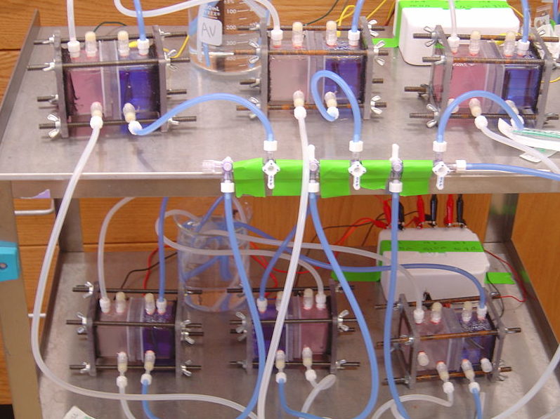
The final product is a complete system capable of introducing separate strains of bacteria to multiple different environments while simultaneously measuring and recording current readings from each. The experimenter specifies the number of bacteria/environment combinations to be run, as well as the initial conditions for each. Data collection and storage is automated, with a computer displaying live current readings and graphing historical current levels. The experimenter can change the conditions of any fuel cell throughout the course of the experiment without affecting other fuel cells. The fuel cells themselves are stand-alone, capable of being treated as individual circuit components.
Specifications
Some experiments can last several days. Measurements must be automated to allow for overnight observation.
s. Odenisis only oxidizes substrates in anaerobic environments. The chambers housing the bacteria must be oxygen free and airtight.
Fuel cells must be capable of being sterilized to prevent contamination
Individual fuel cells must be similar enough to produce consistent results.
Experimenters must have access to the bacterial environment.
Approach
Decomposition into components
Construction of the system was broken down into three distinct parts. The most important components were the fuel cells themselves. Once these devices were built, a measurement system was constructed to sample current readings from each simultaneously. Software was developed to orchestrate these readings, recording and displaying them in real time.
Component descriptions and approaches
Fuel Cells
Fuel cells were constructed to provide an environment in which bacteria could live and produce electric current. After researching various microbial fuel cell designs, we concluded that a two chamber system would best suit our goals.
The simple picture of our design was a hollow tube, sealed at both ends with endplates, and cut in half horizontally to allow for insertion of a semi-permeable membrane. The two halves would then be clamped back together to close the system. Ports needed to be drilled into the walls of the tube to allow for insertion of the anode and cathode, as well as to initially fill the sealed chambers with media and inject bacteria and food. Previous research suggested bubbling gasses into the chambers could improve performance. In the anode chamber, nitrogen was typically bubbled to purge the chamber of oxygen, keeping the bacteria in a controlled anaerobic environment. In the cathode chamber, air was typically bubbled to provide a continuous source of oxygen, ensuring an efficient reduction reaction. We decided to include ports for gas inlet and outlet as well.
Materials for the chamber were then selected. The central tube and endplates were made from polycarbonate. This is a clear, hard plastic that is easily bonded to itself with silicone glue. It has the added benefit of allowing visual monitoring of the chambers, it is easily milled, and it can be autoclaved. Silicone was used in glue form to bond the tubes to their endplates, and it was used in solidified from to construct gaskets which sealed the two chambers together when clamped. The clamping mechanism involved drilling holes through the overlap of the endplates, inserting iron threaded rods down the length of the chambers, and fastening the ends of the rods with wing nuts.
Measurement
We required that our measurement system be automated and capable of monitoring multiple fuel cells at once. Our original goal was to measure and compare output current levels between separate fuel cell environments. We choose to use current as the measured variable since previous studies in s. Onedisis and mutants gave us reasonable expectation values of the current magnitudes we would observe. As these reported current levels were on the order of microamps for similarly sized systems, we decided to purchase a high throughput commercial digital multimeter (DMM) to achieve the desired resolution. Finding a multiplexed system with large quantities of current channels proved difficult, and we adapted our schematic to measure voltage and resistance and then calculate current.
Our final product choice was the Keithley 2700 with a Keithley 7700 multiplexer accessory. This configuration provided 100 nA current resolution while allowing up to 20 devices to be sampled from at once.
We choose to use 470 Ohms as our resistance connecting the anode and cathode of each fuel cell. This choice was based on several considerations. We measured the resistance path from the surface of an anode to the surface of a cathode and found that it ranged from 5-10 Ohms. Our resistance had to be large enough that voltage drops across this internal resistance did not significantly affect the measured voltage drop across our external resistor. We also measured the resistance of the path from anode to cathode through the fuel cells media and membrane. This resistance was highly variable but typically ranged from 15K to 25K. Our external resistance had to be low enough that the vast majority of freed electrons traveled externally rather than through this variable media/membrane path.
Software
The task of our software program was to coordinate measurements through the DMM, record data, and display live data in graphical format. Some members of our team had prior experience with LabVIEW, which we used to develop these routines.
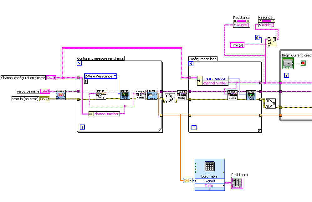
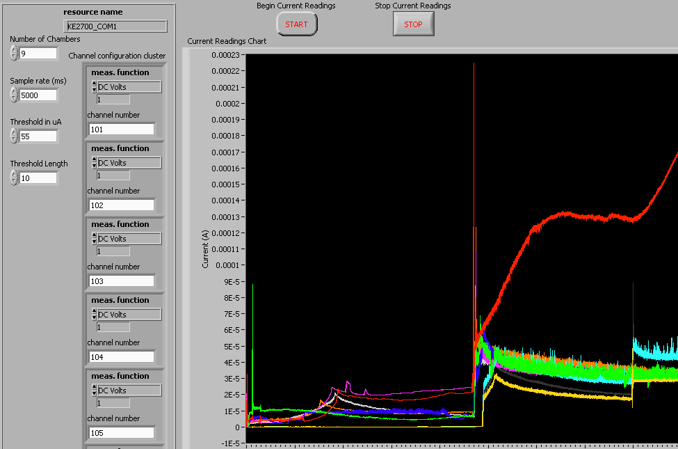
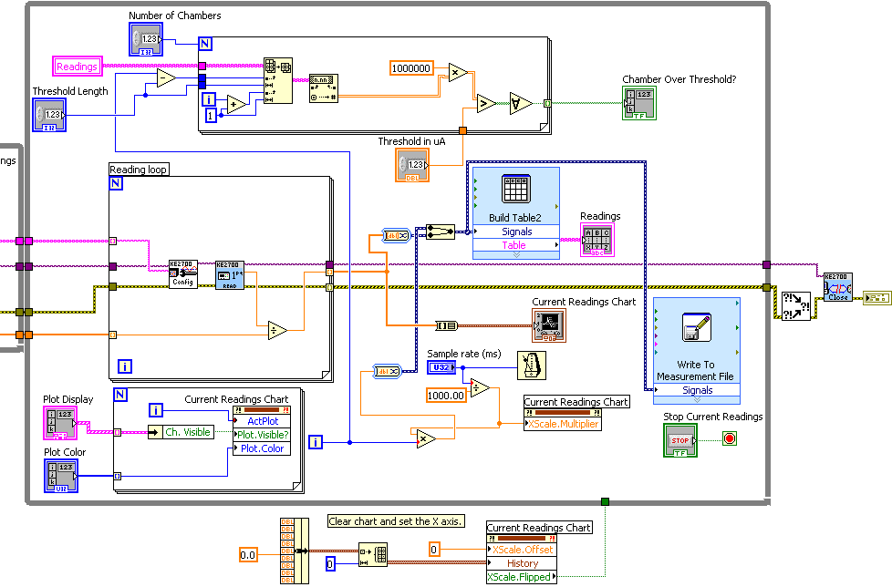
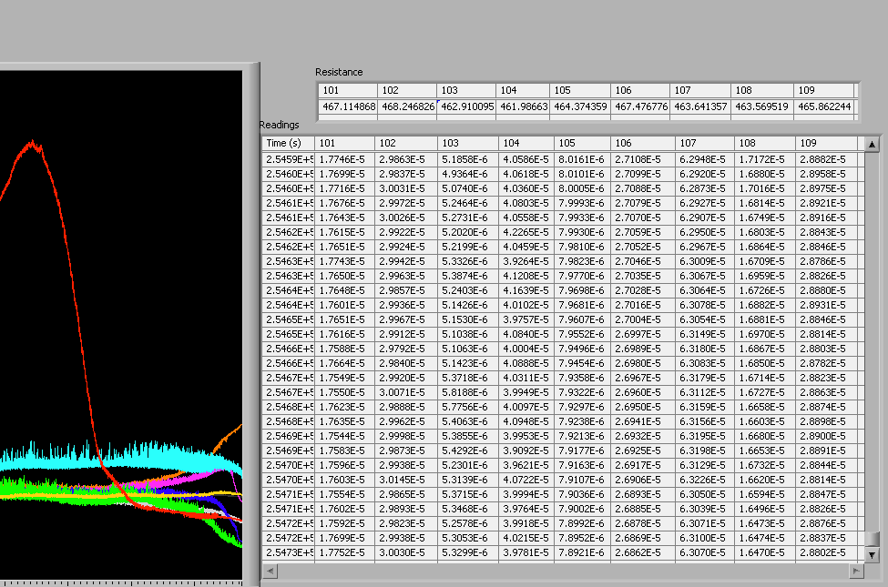
Working with the Keithley DMM, our program first samples resistances across each fuel cell's external resistor. It then switches the DMM measurement channel to voltage and enters a measurement loop. In each loop iteration, voltage samples are taken from all connected fuel cells and are divided by their previously measured resistances. This computed current is displayed in both graphical and tabular format, as well as stored in a .xls file. Current values are compared against a user specified threshold value, and a display indicates which chambers are over threshold. To avoid spikes, this function only returns true if a chamber's current level has been above threshold for the previous ten readings. An iteration ends by waiting for the next multiple of a user specified time. This ensures synchronous measurement intervals.
- In LabVIEW, a block diagram is used to visually write c code. Our block diagram is shown here.
- In Labview, an instrument panel is used to allow users to specify inputs and to display the status of program variables. Our instrument panel is shown here.
|  "
"


