Team:Princeton/ProjectDetails
From 2008.igem.org
(→The Toggle Switch) |
(→The Toggle Switch) |
||
| Line 6: | Line 6: | ||
|} | |} | ||
| | ||
| + | |||
A toggle switch is a bi-stable system where two inputs are responsible for two different outputs - similar to an on/off switch. The system depicted on the right consists of three groups of cells: one pacemaker group (P) and two groups of neurons (B1 and B2). By nature, pacemaker cells do not need to be activated themselves, but can continuously activate B1 and B2. | A toggle switch is a bi-stable system where two inputs are responsible for two different outputs - similar to an on/off switch. The system depicted on the right consists of three groups of cells: one pacemaker group (P) and two groups of neurons (B1 and B2). By nature, pacemaker cells do not need to be activated themselves, but can continuously activate B1 and B2. | ||
Revision as of 04:18, 30 October 2008
PRINCETON IGEM 2008
| Home | Project Overview | Project Details | Experiments | Results | Notebook |
|---|
| Parts Submitted to the Registry | Modeling | The Team | Gallery |
|---|
Contents |
The Toggle Switch
|
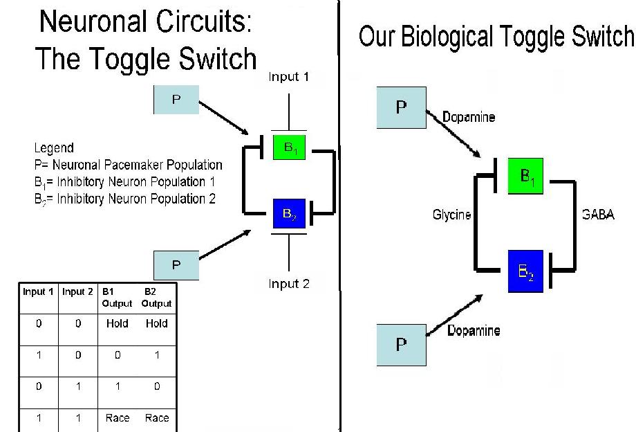
A toggle switch is a bi-stable system where two inputs are responsible for two different outputs - similar to an on/off switch. The system depicted on the right consists of three groups of cells: one pacemaker group (P) and two groups of neurons (B1 and B2). By nature, pacemaker cells do not need to be activated themselves, but can continuously activate B1 and B2.
B1 and B2 consistently inhibit each other, which requires their signals to be able to overcome the excitation of the pacemaker cells. Activation by P allows B1 and B2 to continuously inhibit B1 and B2. When Input 1 is introduced into the system, B1 is inhibited and therefore cannot, in turn, inhibit B2. Thus, we have B2 as an output. Conversely, when Input 2 is applied, B2 is inhibited and B1 is the output.
If at any time both inputs were introduced into the system, the system would enter a race condition. In engineering theory, it is impossible to predict what the outcome of the race would be; in practice, however, because of the nuances in strength and degradation time of the two inhibitory signals, one would eventually win out over the other. For our purposes, one input will be introduced into the system so as to gain a singular output and test the functionality of our design.
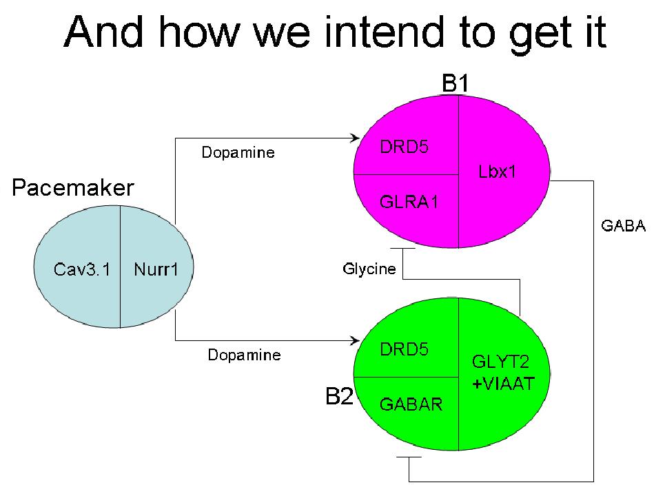
The diagram to the right shows the neurotransmitters we have chosen to control the neuronal toggle switch. In this case, the excitatory signal produced by the pacemaker cells is a result of dopamine, in combination with Dopamine Receptor 5 (D5R) located on the B1 and B2 neurons. Their activation causes the production of glycine by the B2 cells and GABA by the B1 cells. B2 cells are designed to be receptive to inhibition by the neurotransmitter produced by the B1 cells (GABA) and vice versa for B1 cells. When both groups are excited by the pacemaker cells and inhibit one another equally, the system enters into an unpredictable race state. If there is more of one inhibitory neurotransmitter in the system, the group receptive to it will be repressed and the other group will "win". The key to the R/S latch and, in fact, our whole system, is that it is designed in such a way that when the input is taken away, the system will enter a "hold" state during which it will continue its last known state, even in the absence of new signals.
|
Specific genes used to achieve the differentiation of the desired neuron types for the system:
Pacemaker:
- Cav3.1 - Allows for continuous activation in cells, or differentiation into the pacemaker type
- Nurr1 - Dopaminergic
B1:
- DRD5 - Dopamine Receptor 5
- GLRA1 - Glycine Receptor
- Lbx1 - GABAergic
B2:
- DRD5 - Dopamine Receptor 5
- GABAR - GABA Receptor (specific gene still not found due to multiple subunits)
- GLYT2 and VIATT - Glycinergic
Plasmid Designs
We worked on designing and constructing several plasmids this summer. Our plasmids were on the whole designed using PCR SOEing (Splicing by Overlap Extension). The process involves PCRing the pieces of the plasmid insert separately, but adding one or more "overlap" regions to each insert section that consists of the end sequence of the neighboring section.
For example, if the insert to be put into the vector is A-B-C, then A would be PCRed with a bit of the beginning of B added onto the end using a primer overhang. B would be PCRed with a bit of the beginning of C added on (the end of A need not be added onto the beginning of B because B already has an overlap with the beginning of its sequence that was added onto the end of A). Then A could be "SOEed" to B by running a PCR reaction of equimolar amounts of A and B, the forward primer of A and the reverse primer of B. A and B will anneal to each other and acts as primers in addition to the oligos in the reaction. B and C could similarly be SOEed, followed by A-B and B-C. A and B and C could also be SOEed together in a single reaction, with every piece acting as primer, but there are decreasing outputs the more pieces that one attempts to SOE in a single reaction.
A list of plasmids we have designed and worked on is given here, each linking to a design page. Some plasmids were redesigned, and hence appear more than once, with a number tacked on the end. At the top of each page the name of the plasmid is listed, followed by the vector, with the position and names of the restriction sites used to cut, and the insert, similarly marked with restriction sites. If the enzymes do not match it they have compatible overhangs.
PCR SOEing and Sequencing Primers
We created over 100 primers for the construction and sequencing of our plasmids. For the sequences and properties of each primer, as well as which primers were used for which plasmids, click here.
Surface Patterning
Previous Work I - Preparation of Gold Surface for Cell Adhesion
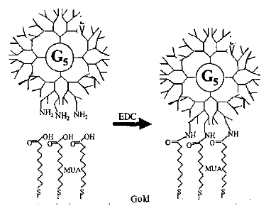
M.B. Shenai et al (2003) have demonstrated a protocol for viable cell adhesion. A layer of chrome or titanium is deposited on a glass slide, followed by the deposition of a layer of gold by electron beam evaporation in the required pattern. Once this surface has been cleaned of organic impurities, it is covered by a 7.5M solution of mercaptoundecanoic acid (MUA), which adheres to the gold and has carboxyl groups on the other end. These groups are activated (using a carbodiimide) and they attach to the amide groups in a synthetic polymer called a dendrimer that forms the final layer on top of the gold. The image below shows a cross-section of the surface once it is ready for the addition of medium and cell adhesion to the dendrimer.
|
The MUA is attached to the gold, while the EDC activates the carboxyl groups of the MUA to attach to the amide groups of the dendrimer.
Previous Work II - Patterning of the Gold Surface
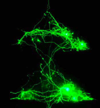
It has been shown that plating neurons in defined patterns gives the emerging neural networks properties that are directly related to those patterns. Assaf Rotem of the Weizmann Institute demonstrated that triangular plating, for example, encourages the propagation of asymmetric signals and directed axonal growth, thereby acting somewhat similar to a diode.
|
The procedure for creating the surface patterns is as follows. The mask design is created on L-Edit, which is a mask-designing software. A neuronal toggle switch is designed to look like this. The idea is not only to preferentially form connections based on neurotransmitters as specified through differentiation of cells, but also by breaking the symmetry of networks by introducing triangles.
Once the pattern is designed, it is used to form gold patterns on a glass slide. The procedure described above is then carried out to attach the thiol, attach the dendrimers, and encourage "selective cell adhesion". For experimental purposes, the pattern shown, and only two triangles connected to each other, will be created.
The Learning Circuit
|
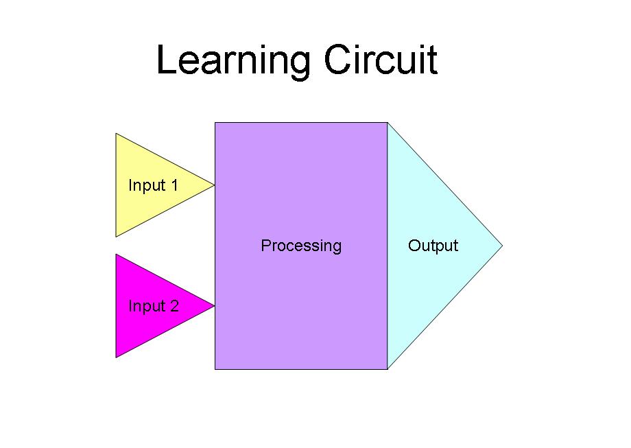
Our goal for the learning circuit was to control long-term potentiation and long-term depression in order to teach a self-formed neuronal network to recognize a desired input. We were also focused on training a neuronal network to recognize a specific stimulus by giving a "correct" response when exposed to the "correct" input. The diagram shown above depicts our desired placement for each step of the process, as the circuit would be coupled with the surface patterning described above.
|
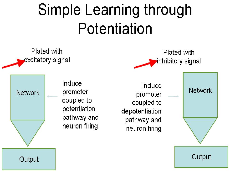
In this diagram, the picture on the left is of a neuronal network that will be plated with a "correct" input to create an excitatory signal. This would cause a cascade of potentiation throughout the network pathway and cause neuronal firing, achieving the desired output. On the right side, the network is plated with a different input inducing an inhibitory signal. That signal causes depotentiation to occur across the network, resulting in the "wrong" output. By building long-term potentiation through bouts of long-term depression, we can hopefully teach the network to recognize the "correct" input.
References
- Nanotexturing Gold Surfaces with Dendrimers for Selective Cell Adhesion
M.B. Shenai et. al; 2003
- Reliable neuronal logic devices from patterned hippocampal cultures (Under Review)
Feinerman, Rotem and Moses; 2008
 "
"
