Team:Heidelberg/Parts/Characterization
From 2008.igem.org
(→oriT R (BBa_J01003)) |
(→oriT R (BBa_J01003)) |
||
| Line 587: | Line 587: | ||
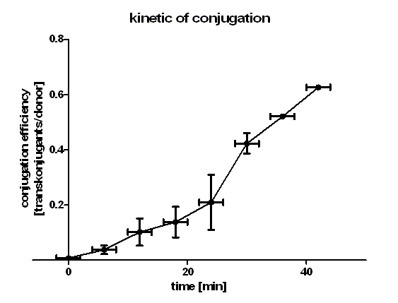
[[Image:HD_kinetic of conjugation.png|center|thumb|500px|'''Figure 1: conjugation kinetic of BBa_J01003 between ''E. coli'' Top10 strains.''' Note that the conjugation efficiency increases with the time allowed for the conjugation to take place.]] | [[Image:HD_kinetic of conjugation.png|center|thumb|500px|'''Figure 1: conjugation kinetic of BBa_J01003 between ''E. coli'' Top10 strains.''' Note that the conjugation efficiency increases with the time allowed for the conjugation to take place.]] | ||
| + | |||
| + | Figure 1 shows that the kinetic of the conjugative plasmid BBa_J01003 has three phases. In the first (0 min to 24 min) and in the third phase (30 min to 42 min) the curve has a smaller slope, whereas the second phase (24 min to 30 min) it has a very big slope. An explanation for this result could be that the cell growth in the first 24 min can be neglected due to the average generation time of E. coli in the LB medium which lies between 20 and 30 minutes whereas in the second phase the growth of E. coli dominates the conjugation process and leads to this deviation from linearity. In this test we used very concentrated bacteria suspension in a small conjugation volume which leads to the observation of conjugation in an approximately linear process in the primary phase. | ||
| + | We have done a linear regression analysis for the first phase (0 min to 24 min) and we calculated the slope for this phase as 0.008397 [transconjugants / donor / min]. We calculated the conjugation rate for BBa_J01003 which is defined as transconjugants / donor / recipient / minutes. The conjugation rate of BBa_J01003 is 1.05 • 10-12 [ml • min-1 • cell-1]. This rate was used by the modeling group as a parameter value. | ||
| + | Figure 1 also shows us that the transport of the plasmid pSB1A2 containing the part BBa_J01003 by conjugation is a very fast process since we got transconjugants in the first minutes of the experiment. Through this experiment we can conclude that the transport of the plasmid pSB1A2 containing BBa_J01003 by conjugation needs only about 2 minutes. | ||
| + | Since we have two conjugative plasmids in our donor cells, we wanted to see which plasmid is preferred to be transported by conjugation. We therefore plated the cells in the test C (see table 2) also on agar plates containing chloramphenicol + kanamycin (CK) and chloramphenicol + kanamycin + ampicillin (CKA) to select for transconjugants getting pUB307 and both plasmids. | ||
| + | |||
| + | Table 2 | ||
Revision as of 13:09, 28 October 2008


Part Characterization
lambda cI (BBa_K150004)
cI protein
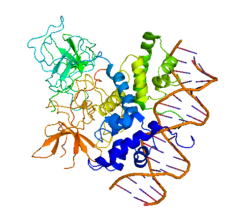
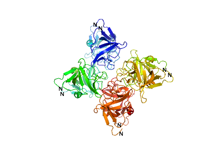
Bacteriophage λ cI exists as an inactive monomer at very low concentrations (<10-9 M) but forms functional homodimers at physiological concentrations that remarkably lack a global symmetry [1]. It consists of 236 amino acids, although 237 amino acids are translated since the initiator methionine is removed by the host. Although λ cI is commonly called a repressor because of its negative regulatory functions at oL and oR, cI protein acts also as a positive regulator of gene transcription and can activate transcription of its own gene through the pRM promoter in bacteriophage λ. In genetic and biochemical studies as well as through the crystal structure it has been shown, that the carboxy-terminal domain of the cI protein contains the major sites for dimerization and oligomerization [2, 3]. The cI protein has a two-domain structure with an N-terminal portion involved in DNA binding, and a C-terminal domain that mediates dimer formation, dimer-dimer interaction, and self-cleavage. The self-cleavage reaction is triggert when the lysogenic cell suffers DNA damage and depends upon an activated form of the bacterial RecA protein [2, 4-6]. The ‘hinge region’ connecting both domains contains a conserved site that can undergo this RecA-mediated autodigestion resulting in inactivation of the repressor by separating the N-terminal from the C-terminal domain of the repressor [4, 7]. The cI protein binds symmetrically to DNA, so that each amino-terminal domain contacts a similar set of bases. The N-terminal DNA-binding domain is made up of 5 α-helices of which helix 2 and helix 3 (the helix-turn-helix motif) are involved in nucleotide sequence specific DNA recognition and binding to the major groove of DNA [8-11].
Function of cI protein in bacteriophage λ
The cI repressor in bacterophage λ is the key component of a ‘genetic switch’ that enables the phage to transition from lysogenic growth to lytic development. The cI protein binds the oL and oR operator which overlap with the pL and pR promoter (the lytic promoters). This binding allows the maintenance of the lysogenic state to be governed by cI alone. As soon as cI is inactivated, e.g., by the SOS response after UV damage or other agents that cause DNA damage, the lytic development follows [12]. The two operators oL and oR both contain three binding sites for cI protein. In each case, site 1 (i.e. oL1 and oR1) has a ~10-fold greater affinity than the other sites for cI protein. The repressor, therefore, always binds first to oL1 and oR1 and than binds to the other sites in the operator in a cooperative manner [13, 14]. The carboxy-terminal domains of the repressor dimmers mediate this cooperativity which improves the specificity and strength of the cI DNA binding, enabling strong repression of the lytic promoters [15]. Furthermore, another cooperative interaction between these two sets of tetramers bound to oL and oR, 2.4 kb apart, leads to the formation of a DNA loop held by a cI octamer, i.e. two interacting tetramers, that enhances repression of the early promoters [16-19]. In this DNA-multiprotein complex, the cI dimer bound at oR2 represses pR and at the same time also stimulates pRM transcription, thus activating cI synthesis in a repressed prophage by a positive autoregulatory loop [20-22]. As the cI concentration increases because of pRM activation, two additional cI dimers are recruited to bind oL3 and oR3 to further stabilize the oL – oR loop. In this context, cI overexpression is prevented by the binding of cI to oR3 which represses pRM [17, 19]. This positive and negative autoregulation at pRM by cI ensures a narrow range of cI repressor level to be maintained, which is optimum for stable lysogeny but is at the same time adjusted low enough for efficient induction of the lysogen. By repressing transcription from the pR promoter not only expression of genes in that operon is inhibited but also phage DNA replication by preventing transcriptional activation of λ ori, the site where phage DNA replication is initiated [23]. Even if O and P functions are present this inhibition occurs and appears to be critical for establishing a lysogen [24, 25]. The stable lysogen produces sufficient repressor not only to block prophage lytic development but also to block lytic development of any extraneous infection phage, thus imparting immunity to the lysogen against lytic superinfection [26].
Characterization of cI (BBa_K150004)
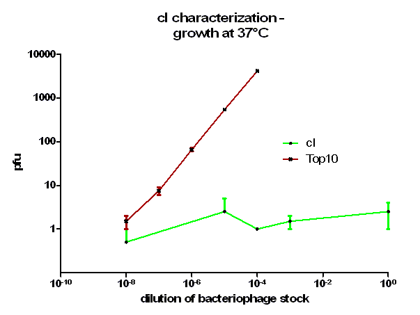
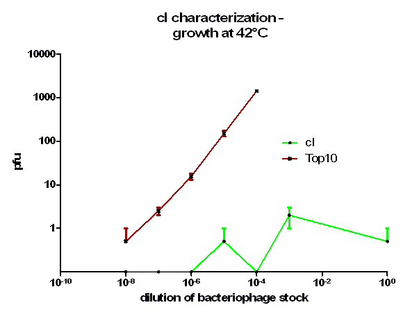
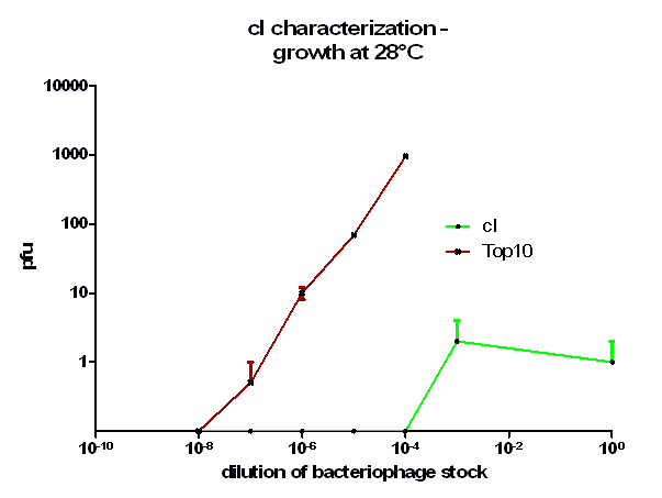
For the characterization of λ cI protein its ability to repress lytic development of bacteriophage λ was measured over a range of temperature from 28 °C to 42 °C in a phage burst experiment. If the used cI is functional no plaques should appear in a lawn of cells harbouring this cI when infected with a phage that lacks its natural cI. In control cells in contrast every of this virulent particles should lead to a plaque.
Protocol
Preparation of plating bacteria A overnight culture of the appropriate E. coli strain was grown in LB medium containing 10 mM MgSO4 and 0.2 % maltose at 30 °C to reduce the amount of cell debris in the medium. For this characterization E. coli Top10 and E. coli Top10 with transformed cI were used. The added maltose leads to a substantial induction of the maltose operon including the lamb gene, which encodes the cell surface receptor to which bacteriophage λ binds. After harvesting the cells at 3000g for 10 minutes they were resuspended in 10 mM MgSO4 and diluted to a final concentration of 2.0 OD600. The suspension of plating bacteria was stored at 4 °C for up to 1 week.
Bacteriophage λ plaque assay
Tenfold serial dilutions of the bacteriophage λ stocks were prepared. In this case a bacteriophage mutant was used lacking a functional cI which would therefore always lead to plaques. From these dilutions 100 µl were mixed with the same amount of plating bacteria, incubated for 20 minutes at 37 °C to allow the bacteriophage particles to adsorb to the bacteria, this mixture than added to 3 ml molten top agar which was kept liquid at 48 °C and the entire contend poured onto a agar plate. After harden of the top agar the inverted plates were incubated at indicated temperatures over night. On the next day plaques could be counted.
Results
As it can be seen in figure 3 – 5 the cells harbouring the part BBa_K150004 are not lysed by the used phage. This means that the constructed cI protein generator successfully expresses high levels of cI protein which is functional. Through the use of different temperatures it could be shown that the ability of the used cI protein to repress lytic development is not dependent of the temperature.
[1] S. Stayrook, P. Jaru-Ampornpan, J. Ni, A. Hochschild, M. Lewis, Crystal structure of the lambda repressor and a model for pairwise cooperative operator binding, Nature 452 (2008) 1022-1025.
[2] C.O. Pabo, R.T. Sauer, J.M. Sturtevant, M. Ptashne, The lambda repressor contains two domains, Proc Natl Acad Sci U S A 76 (1979) 1608-1612.
[3] C.E. Bell, P. Frescura, A. Hochschild, M. Lewis, Crystal structure of the lambda repressor C-terminal domain provides a model for cooperative operator binding, Cell 101 (2000) 801-811.
[4] J.W. Little, Autodigestion of lexA and phage lambda repressors, Proc Natl Acad Sci U S A 81 (1984) 1375-1379.
[5] R.T. Sauer, M.J. Ross, M. Ptashne, Cleavage of the lambda and P22 repressors by recA protein, J Biol Chem 257 (1982) 4458-4462.
[6] R.T. Sauer, C.O. Pabo, B.J. Meyer, M. Ptashne, K.C. Backman, Regulatory functions of the lambda repressor reside in the amino-terminal domain, Nature 279 (1979) 396-400.
[7] J.W. Little, LexA cleavage and other self-processing reactions, J Bacteriol 175 (1993) 4943-4950.
[8] C.O. Pabo, M. Lewis, The operator-binding domain of lambda repressor: structure and DNA recognition, Nature 298 (1982) 443-447.
[9] L.J. Beamer, C.O. Pabo, Refined 1.8 A crystal structure of the lambda repressor-operator complex, J Mol Biol 227 (1992) 177-196.
[10] A. Hochschild, Transcriptional activation. How lambda repressor talks to RNA polymerase, Curr Biol 4 (1994) 440-442.
[11] C.O. Pabo, R.T. Sauer, Transcription factors: structural families and principles of DNA recognition, Annu Rev Biochem 61 (1992) 1053-1095.
[12] A. Hochschild, The lambda switch: cI closes the gap in autoregulation, Curr Biol 12 (2002) R87-89.
[13] A.D. Johnson, B.J. Meyer, M. Ptashne, Interactions between DNA-bound repressors govern regulation by the lambda phage repressor, Proc Natl Acad Sci U S A 76 (1979) 5061-5065.
[14] M. Ptashne, Genetic switch: phage lambda revisited, 2nd ed., Cold Spring Harbor Laboratory Press, Cold Spring Harbor, NY, 2004.
[15] I.B. Dodd, K.E. Shearwin, J.B. Egan, Revisited gene regulation in bacteriophage lambda, Curr Opin Genet Dev 15 (2005) 145-152.
[16] I.B. Dodd, A.J. Perkins, D. Tsemitsidis, J.B. Egan, Octamerization of lambda CI repressor is needed for effective repression of P(RM) and efficient switching from lysogeny, Genes Dev 15 (2001) 3013-3022.
[17] I.B. Dodd, K.E. Shearwin, A.J. Perkins, T. Burr, A. Hochschild, J.B. Egan, Cooperativity in long-range gene regulation by the lambda CI repressor, Genes Dev 18 (2004) 344-354.
[18] B. Revet, B. von Wilcken-Bergmann, H. Bessert, A. Barker, B. Muller-Hill, Four dimers of lambda repressor bound to two suitably spaced pairs of lambda operators form octamers and DNA loops over large distances, Curr Biol 9 (1999) 151-154.
[19] S.L. Svenningsen, N. Costantino, D.L. Court, S. Adhya, On the role of Cro in lambda prophage induction, Proc Natl Acad Sci U S A 102 (2005) 4465-4469.
[20] B.J. Meyer, M. Ptashne, Gene regulation at the right operator (OR) of bacteriophage lambda. III. lambda repressor directly activates gene transcription, J Mol Biol 139 (1980) 195-205.
[21] D. Jain, B.E. Nickels, L. Sun, A. Hochschild, S.A. Darst, Structure of a ternary transcription activation complex, Mol Cell 13 (2004) 45-53.
[22] B.E. Nickels, S.L. Dove, K.S. Murakami, S.A. Darst, A. Hochschild, Protein-protein and protein-DNA interactions of sigma70 region 4 involved in transcription activation by lambdacI, J Mol Biol 324 (2002) 17-34.
[23] M.E. Furth, W.F. Dove, B.J. Meyer, Specificity determinants for bacteriophage lambda DNA replication. III. Activation of replication in lambda ric mutants by transcription outside of ori, J Mol Biol 154 (1982) 65-83.
[24] K. Mensa-Wilmot, K. Carroll, R. McMacken, Transcriptional activation of bacteriophage lambda DNA replication in vitro: regulatory role of histone-like protein HU of Escherichia coli, EMBO J 8 (1989) 2393-2402.
[25] M.S. Wold, J.B. Mallory, J.D. Roberts, J.H. LeBowitz, R. McMacken, Initiation of bacteriophage lambda DNA replication in vitro with purified lambda replication proteins, Proc Natl Acad Sci U S A 79 (1982) 6176-6180.
[26] D.L. Court, A.B. Oppenheim, S.L. Adhya, A new look at bacteriophage lambda genetic networks, J Bacteriol 189 (2007) 298-304.
[27] C.E. Bell, M. Lewis, Crystal structure of the lambda repressor C-terminal domain octamer, J Mol Biol 314 (2001) 1127-1136.
oriT R (BBa_J01003)
We have characterized the oriT BBa_J01003 in a conjugation system in which pUB307 is used as helper plasmid and E. coli as donor and recipient cells. We measured quantitatively the conjugative competence of oriT BBa_J01003 by conjugation between different strains, at different temperatures and with different donor/recipient ratios. We also compared the conjugation kinetics of BBa_BBa_J01003 and pUB307 quantitatively.
The part oriT R BBa_J01003 was cotransformed together with pUB307 (helper plasmid) into E. coli strain Top10. These cells therefore became conjugation donor and have a kanamycin (from pUB307) and ampicillin (from BBa_J01003) resistance. The recipient cells have the plasmid pBAD33 with a chloramphenicol resistance. After mixing both cells types the conjugation starts and BBa_J01003 as well as pUB307 can be transported. The helper plasmid pUB307 can still be transported since it still contains its oriT region. The transconjugants which have received BBa_J01003 through the conjugation have ampicillin and chloramphenicol resistance and can therefore be easily selected.
Test 1 Conjugation kinetics of oriT BBa_J01003 between E. coli Top10
On the first day we inoculated LB + antibiotics medium with a single colony or from a glycerol stock. For this test we used donor and the recipient cells that were both E. coli Top10. On the second day we washed the cells of the overnight culture twice with LB medium, transferred the donor cell suspension to the pellet of the recipient cells and resuspended the recipient cells in this medium. After another centrifugation step we resuspended the pellet which now is a mixture of donor and recipient cells in 100 µl LB medium without antibiotics. We than transferred the cell suspension on a membrane filter, which was placed on LB plates before and incubated these plates at 37°C for 0, 6, 12, 18, 24, 30, 36, 42 minutes. Afterwards the membrane was put into 1 ml LB medium and the cells resuspended by vortexing for 30 seconds. The cell suspension was diluted 10-5 and plated on the LB / ampicillin + chloramphenicol (CA) plates. The plates were incubated at 37 °C overnight and on the third day the colonies could be counted. We have done this test thrice independently and calculated the conjugation efficient which is defined as [transconjugants per ml] / [donor per ml] from this assay. To count the donor and recipient cell density small aliquots of the used suspensions were diluted 10-7 and plated on agar plates containing kanamycin + ampicillin for donor cells and chloramphenicol for the recipients.
Table 1
Figure 1 shows that the kinetic of the conjugative plasmid BBa_J01003 has three phases. In the first (0 min to 24 min) and in the third phase (30 min to 42 min) the curve has a smaller slope, whereas the second phase (24 min to 30 min) it has a very big slope. An explanation for this result could be that the cell growth in the first 24 min can be neglected due to the average generation time of E. coli in the LB medium which lies between 20 and 30 minutes whereas in the second phase the growth of E. coli dominates the conjugation process and leads to this deviation from linearity. In this test we used very concentrated bacteria suspension in a small conjugation volume which leads to the observation of conjugation in an approximately linear process in the primary phase. We have done a linear regression analysis for the first phase (0 min to 24 min) and we calculated the slope for this phase as 0.008397 [transconjugants / donor / min]. We calculated the conjugation rate for BBa_J01003 which is defined as transconjugants / donor / recipient / minutes. The conjugation rate of BBa_J01003 is 1.05 • 10-12 [ml • min-1 • cell-1]. This rate was used by the modeling group as a parameter value. Figure 1 also shows us that the transport of the plasmid pSB1A2 containing the part BBa_J01003 by conjugation is a very fast process since we got transconjugants in the first minutes of the experiment. Through this experiment we can conclude that the transport of the plasmid pSB1A2 containing BBa_J01003 by conjugation needs only about 2 minutes. Since we have two conjugative plasmids in our donor cells, we wanted to see which plasmid is preferred to be transported by conjugation. We therefore plated the cells in the test C (see table 2) also on agar plates containing chloramphenicol + kanamycin (CK) and chloramphenicol + kanamycin + ampicillin (CKA) to select for transconjugants getting pUB307 and both plasmids.
Table 2
 "
"
