|
Network Design - Part 2
Creating an oscillating system
Already existing genetic oscillators and their limits
Designing a simple genetic network that presents an oscillatory behavior is one of the first challenge synthetic biology overcame. More or less successfully. We can count more than ten synthetic genetic oscillators that have varied period and mechanisms. [http://www.ncbi.nlm.nih.gov/pubmed/16604190?ordinalpos=2&itool=EntrezSystem2.PEntrez.Pubmed.Pubmed_ResultsPanel.Pubmed_DefaultReportPanel.Pubmed_RVDocSum Raúl GUANTES and Juan F. POYATOS (2006)] studied the most simple oscillators composed of two elements while [http://www.ncbi.nlm.nih.gov/pubmed/10659856?ordinalpos=10&itool=EntrezSystem2.PEntrez.Pubmed.Pubmed_ResultsPanel.Pubmed_DefaultReportPanel.Pubmed_RVDocSum Michael B. ELOWITZ and Stanislas LEIBLER (2000)] designed the more complex "repressilator" (Table 1), to quote only the best known.
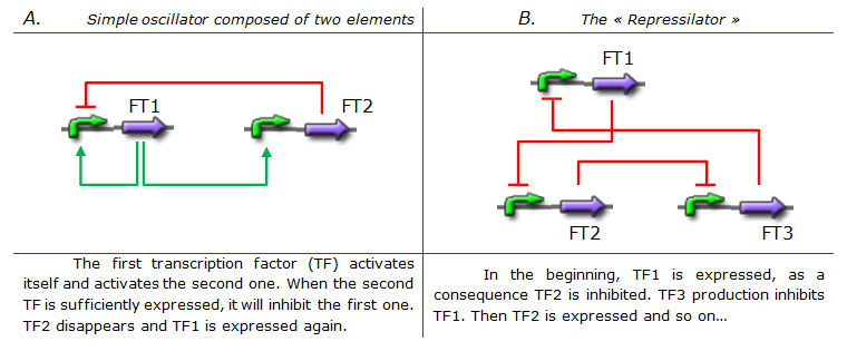 Tab 1. Two examples of genetic oscillators. A : a simple oscillator composed of two elements. B : the repressilator. (Legend : Green arrow : Activation. Red blunt arrow : Inhibition) Both oscillators work : we can observe oscillations but only a limited number of cycles. Actually, they always reach a steady-state because the degradation/dilution rate is often too low : at the end of each cycle, the conditions are not exactly the initial conditions. Experimentally, the longer is the period the more cycles we can observe.
Design of our genetic oscillator : The Feed Forward Loop
We want to design a simple oscillator that oscillates during as many cycles as possible. We propose a system based on an oscillator composed of two elements (Network 1) on which we added a delay at the end of each cycle.
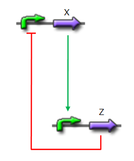 Network 1. Simple oscillator composed of two elements Uri ALON described genetic network motifs that generate a delay. Those motifs are the type 1 coherent Feed Forward Loop (C1-FFL).
↓ More on Feed Forward Loop ↑
Definition of a FFL
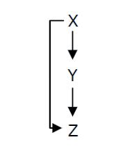 Fig. 1 : Structure of a type 1 coherent Feed Forward Loop
A Feed-Forward Loop is a genetic network composed of three nodes. This strong network motif is composed of a transcription factor X that regulates a second transcription factor, Y, and both X and Y regulate Z (Figure 1).
The different types of FFL
Depending on the type of regulations between the different nodes, we can define eight types of FFL that can be classified into two groups : coherent and incoherent FFLs. In coherent FFLs, the indirect path has the same overall sign as the direct path. The most abundant FFL is the type-1 coherent FFL (C1-FFL) (Figure 1).
The type 1 coherent Feed Forward Loop with an OR gate introduces a delay after the extinction of the signal
 Fig. 2 : The C1-FFL with OR logic in the flagella system of E. coli. 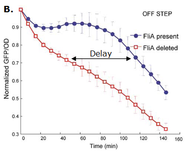 Fig. 3 : Promoter dynamics after an OFF step of X, in the presence of Y. The results are shown for the wild-type bacterium, and for a bacterium in which the gene for Fli1 was deleted from the genome. The FFL generates a delay after an OFF step of X
In addition to the signs of the edges, to understand the dynamics of the FFL, we must also know how the inputs from the two regulators X and Y are integrated at the promoter of the gene Z. Uri ALON considers that there are two biologically reasonable logic functions : "AND" logic, in which both X and Y activities are need to be high in order to turn on Z expression and "OR" logic in which either X or Y is sufficient (Figure 2).
If the input function of the promoter of the gene Z is "OR", Z is expressed when X activity is high. There is no delay following the expression of X. But when X is not expressed anymore, its concentration decreases and reach the activation threshold of Y and Z. Y is not expressed anymore but as the concentration decreases, Z is still expressed. The OR-gate C1-FFL allow the gene Z to be expressed about one more hour after the gene X is OFF. (Figure 3)
Bibliography :
- [http://www.nature.com/ng/journal/v31/n1/abs/ng881.html Shen-Orr et al. (2002)]
- [http://www.ncbi.nlm.nih.gov/pubmed/14607112?ordinalpos=1&itool=EntrezSystem2.PEntrez.Pubmed.Pubmed_ResultsPanel.Pubmed_DefaultReportPanel.Pubmed_RVDocSum Mangan et al. (2003)]
- [http://www.ncbi.nlm.nih.gov/pubmed/14530388?ordinalpos=2&itool=EntrezSystem2.PEntrez.Pubmed.Pubmed_ResultsPanel.Pubmed_DefaultReportPanel.Pubmed_RVDocSum Mangan et al. (2003)]
- [http://www.pubmedcentral.nih.gov/articlerender.fcgi?tool=pubmed&pubmedid=16729041 Kalir et al. (2005)]
|
We will use one of those network to increase the run of each period and permit more oscillations (Network 2).
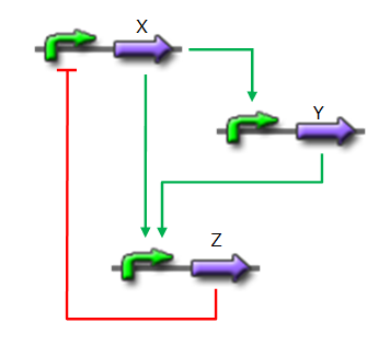 Network 2. Our oscillator : a C1-FFL increase the length of each period Implementation of the core system
[http://www.ncbi.nlm.nih.gov/pubmed/16729041?ordinalpos=1&itool=EntrezSystem2.PEntrez.Pubmed.Pubmed_ResultsPanel.Pubmed_DefaultReportPanel.Pubmed_RVDocSum Shiraz Kalir et al. (2004)] studied the complex network of gene that lead to the synthesis of E. coli flagella.
A C1-FFL is present in this network.
↓ Click here to know more about E. coli flagella. ↑
Description of the genetic pathway that lead to flagella assembly
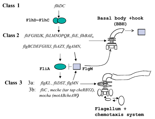 Figure 1 : The genetically defined hierarchy of the flagellar operons in Escherichia coli. The construction of E. coli flagellar system is organized into a complex hierarchy. The different parts of the flagella are successively assembled parts by parts. This architecture is also present in the network of genes that contributes to its set-up.
A global transcription factor FlhDC activates the synthesis of the flagella. This class 1 gene encodes a protein that activates the expression of class 2 genes. Those genes lead to the construction of the basal body of the flagella and its hook. Then FliA, a protein coded by a class 2 gene activates, with FlhDC to the expression of class 3 genes (Figure 1).
The expression of the flagellar genes is precisely ordered
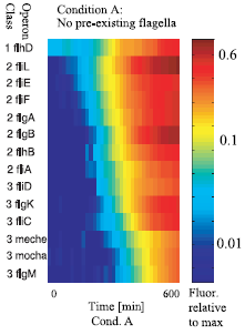 Figure 2 : The sequential expression of flagellar genes The observed order correponds to the spatial position of the gene products during flafellar motor assemblu, going from the cytoplasmic to the extracellular sides.
A quantitative blueprint of the dynamics of the flagella gene network
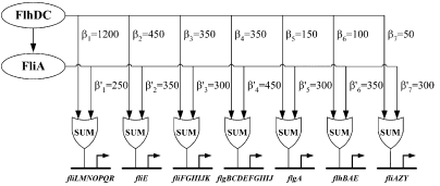 Figure 3 : Quantitative blueprint of the dynamics of class 2 genes of the flagella gene network. β is the activation coefficient corresponding to a transcription factor and a promoter (unit : GFP/OD).
[http://www.ncbi.nlm.nih.gov/pubmed/15186773?ordinalpos=2&itool=EntrezSystem2.PEntrez.Pubmed.Pubmed_ResultsPanel.Pubmed_DefaultReportPanel.Pubmed_RVDocSum| Kalir et al. (2004)] evaluated the strength of the interactions between the different transcription factors fliA and flhDC and the class 2 promoters. They established a quantitative blueprint, considering the strength of the interactions and the functions that integrate multiple input (Figure 3). The structure of this network is typically a Multiple Output FFL, each class 2 gene is regulated by both flhDC and fliA, which is itself regulated by flhDC. This network is the logic circuit that can generate a FIFO behavior.
They determined that the input function for fliL promoter is a SUM gate in relation to FliA and FlhDC.
It means that: Promoter_Activity([FlhDC],[FliA]) = Promoter_Activity([FlhDC],0) + Promoter_Activity(0,[FliA])
The existence of a SUM input function for the other promoters has not been demonstrated but Uri ALON and his team assume that all the class 2 promoters have the same behavior. This is the first condition to create a FIFO.
The coefficients of activation for fliL, flgA and flhB are ordered in the right way to behave as a FIFO :
β1<β5<β6 and β'1>β'5>β'6
The dynamics is easily tunable, which is a great tool for engineering
The model suggests that, in order to change the response time, one can change the numbers on the arrows. For the earliest promoter, fliL, decreasing β1 should make the rise time longer and the maximal expression lower compared to the wild-type promoter. To experimentally change β1, Shiraz KALIR and Uri ALON inserted point mutations in the FlhDC binding site of the fliL promoter. Those mutations made the promoter activity later and weaker.
Bibliography
- [http://www.sciencemag.org/cgi/content/abstract/292/5524/2080| Kalir et al. (2001)]
- [http://www.ncbi.nlm.nih.gov/pubmed/15186773?ordinalpos=2&itool=EntrezSystem2.PEntrez.Pubmed.Pubmed_ResultsPanel.Pubmed_DefaultReportPanel.Pubmed_RVDocSum| Kalir et al. (2004)]
|
- X is flhDC, the master regulator of the synthesis of the flagella. It is associated to its natural promoter.
- Y is fliA, another transcription factor that regulates the expression of a large amount of flagellar genes. fliA is also associated with its natural promoter.
- For Z, we need a protein that inhibits the expression of flhDC. We considered two possibilities. First of all, we planned to use tetR, and the appropriate promoter before flhDC. But, once again, in a concern to use as many "natural" BioBricks, we decided to use proteins that naturally inhibits the expression of flhDC, such as envZ and ompR. The mechanism of inhibition is quite well-known. envZ phosphorylates OmpR which becomes active. OmpR-P strongly inhibits the expression of flhDC. [http://www.ncbi.nlm.nih.gov/pubmed/18193944?ordinalpos=1&itool=EntrezSystem2.PEntrez.Pubmed.Pubmed_ResultsPanel.Pubmed_DefaultReportPanel.Pubmed_RVDocSum Antoine Giraud et al.(2008)] discribed a specific mutant, envZ* that phosphorylates very efficiently ompR. We chose envZ* for Z because it introduces another delay, as envZ* works through over-phophorylation of ompR, which in turns represses flhDC. For Z promoter, we chose one of the promoter controlling the expression of one of the flagellar gene that are regulated by both FliA and FlhDC. We chose the promoter of FlhB because it is the gene that is lastly activated. As a consequence, it increases the length of each cycle. Of course, to make the oscillations observable, we decided to put EnvZ and GFP under the control of the same promoter.
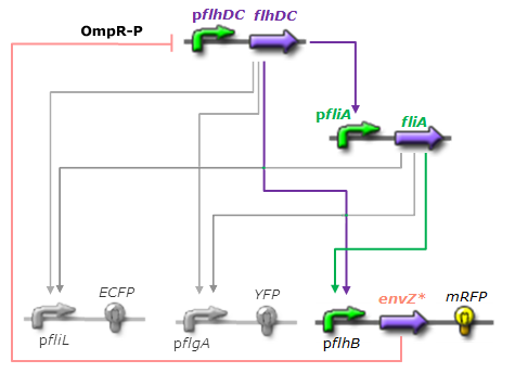 Network 3. Final Design of the core system. Limits of our network
Intuitively, it seems that there is a range of parameters that permits oscillations. However, an analysis of the core system highlighted the fact that it could hardly have an oscillating dynamics (see figure: Simulation of the core system).
Among the alternatives we studied, the system that could most probably oscillate is a HSL mediated simple oscillator that uses the quorum sensing to produce both a delay and the synchronization at the population level.


|
 "
"


