Team:UC Berkeley Tools/Project
From 2008.igem.org
The Project
Genomics has reached the stage at which the amount of DNA sequence information in existing databases is quite large. Synthetic biology now is using these databases to catalog sequences according to their functionality and therefore creating standard biological parts which can be used to create large systems.
As these databases grow, the need for integrated tools that perform complex operations, organize information, and automate regular processes is becoming increasingly obvious. The synthetic biology community could be better-served with the development of flexible tools which not only permit access and modification to that data but also allow one to perform meaningful manipulation and use of that information in an intelligent and efficient way. These tools need to be useful to biologists working in a laboratory environment while leveraging the experience of the larger CAD community.
This project develops a toolset called "Clotho" which provides a variety of design views and tools to aid biologists to modify existing synthetic biological systems as well as create new ones. These tools differ from current offerings in this area in that they not only provide the needed tools to manipulate designs in one complete system but also provide unique ways in which to visualize the design as well as a number of connections to both local and global part repositories.
Platform Based Design
Due to the increased complexity, heterogeneity, and time-to-market concerns currently facing embedded electronic design, the EDA community is facing a crisis. In order to deal with this crisis, a variety of Electronic System Level (ESL) methodologies are emerging. One popular approach is Platform-Based Design (PBD).
PBD is concerned with what is termed the orthogonalization of concerns <ref name="orth">K. Keutzer, S. Malik, R. Newton, J. Rabaey, and A. Sangiovanni-Vincentelli. System level design: Orthogonolization of concerns and platform-based design. IEEE Transactions on Computer-Aided Design of Integrated Circuits and Systems, 19(12), December 2000.</ref>. These concerns are:
- Functionality (what something does) and Architecture (how it does it). For example, multiplication functionally is the same whether implemented as a series of adders or a dedicated multiplier. This separation goal should be of use as well to synthetic biologists.
- Behavior (Semantics) and Performance Indices (Latency, Throughput, etc). Behavior defines how a device operates (bus protocol for example). Performance is a cost of that behavior (bus transaction latency). Again, this may be of use in describing biological systems.
- Computation, Communication, Coordination. How things compute should be separate from how they interact (communicate) with other aspects of the system, and both computation and communication should be separate from the scheduling mechanisms.
By keeping these issues separate, the now modular design allows for a smoother verification process, reuse, and abstraction. These goals are also of use to the synthetic biological community if predictive, large scale synthetic designs are desired.
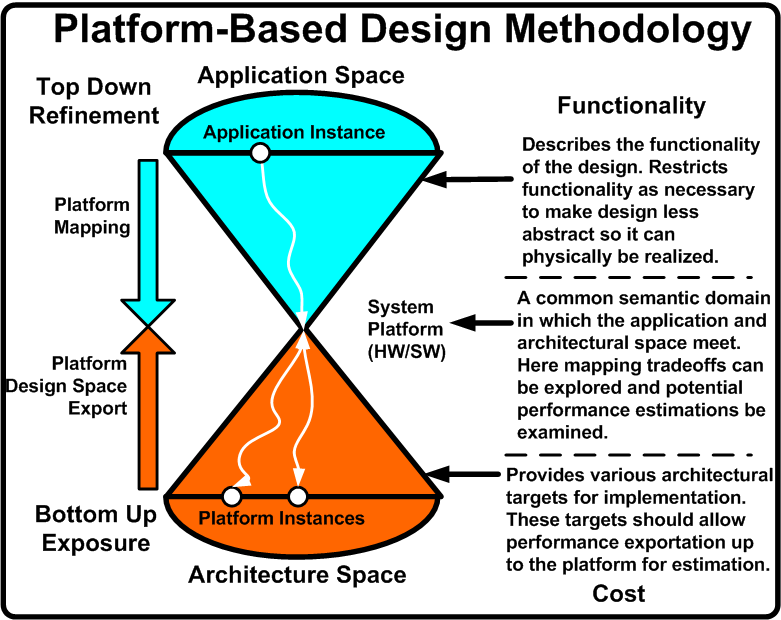
In order to achieve these goals, PBD is a three stage process: top down application development, bottom up performance exposure, and defining a common semantic meeting point to explore functionality and architecture mappings. Figure 1 illustrates this methodology and provides the needed description. <ref name="metro">F. Balarin, Y. Watanabe, H. Hsieh, L. Lavagno, C. Passerone, and A. Sangiovanni-Vincentelli. Metropolis: An integrated electronic system design environment. Computer, 36(4):45–52, 2003.</ref>, <ref name="date04">D. Densmore, S. Rekhi, and A. Sangiovanni-Vincentelli. Microarchitecture development via metropolis successive platform refinement. In Design Automation and Test in Europe (DATE), February 2004.</ref>, and <ref name="DVCon">A. Davare, D. Densmore, T. Meyerowitz, A. Pinto, A. Sangiovanni-Vincentelli, G. Yang, H. Zeng, and Q. Zhu. A next-generation design framework for platform-based design. In Conference on Using Hardware Design and Verification Languages (DVCon), February 2007.</ref> are all successful applications of PBD in embedded electronics.
What follows is a breakdown of the three major aspects of PBD along with how these can be used in the design of synthetic biological systems.
Functionality
Functionality in PBD purely describes the behavior the desired design should exhibit. It makes no association with the underlying mechanisms that will be used to physically implement the functionality. For embedded electronic systems, models of computation (MoCs) such as Kahn Process Networks, Finite State Machines, Dataflow Networks, Petri Nets, etc are typically used to this end. These are mathematical descriptions which can be analyzed for various properties such as liveness, state reachability, and schedulabilty.
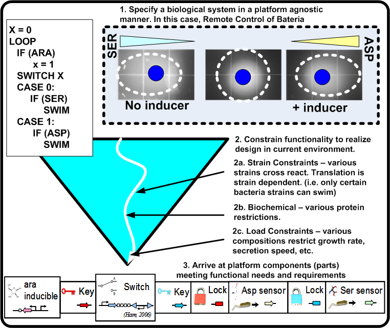
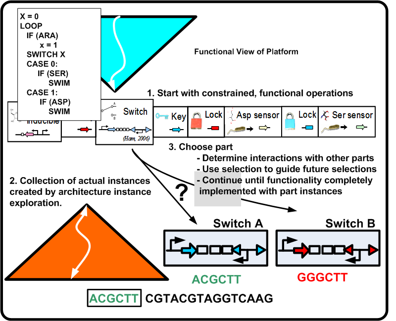
For synthetic biological systems, the ways to describe desired functionality are still in their infancy. For example, while NOR functionality is well understood in a digital logic context, a NOR gate's operation and production in a synthetic biological context depends heavily on the proteins and other chemicals involved. Capturing functional descriptions will prove to be an important part in the development of any design methodology. Figure 2 illustrates a potential process a functional description could go through to constrain itself to map to a platform. Here, Remote Control of Bacteria is shown as a pseudo code initial description. In the event that the inductor Arabinose (ARA) is present, bacteria swim toward Aspartic acid (ASP), otherwise they swim toward Serine (SER). The figure shows the various classes of constraints that direct the functionality toward a particular platform.
Figure 3 illustrates BioJADE's (to be discussed in Section 4) vision of what a the functional space might look like from a CAD perspective. The functional aspect view shows the arrangement of promoters and the genes which they act upon, and the connections between regulatory proteins and the promoters which they affect. In addition, functional network allows the input of molecular species and reactions between molecules and proteins. The designer can perform operations such as changing terminator efficiency or optimize binding strength. These relationships can be seen as functional constraints.
Architecture
In PBD for electronic systems, architectures provide services which then incur a particular cost if used. The process of selecting an individual architecture instance is then observing which collection of platform components implement the desired functionality at a cost acceptable to the designer (low power, rapid execution time, etc).
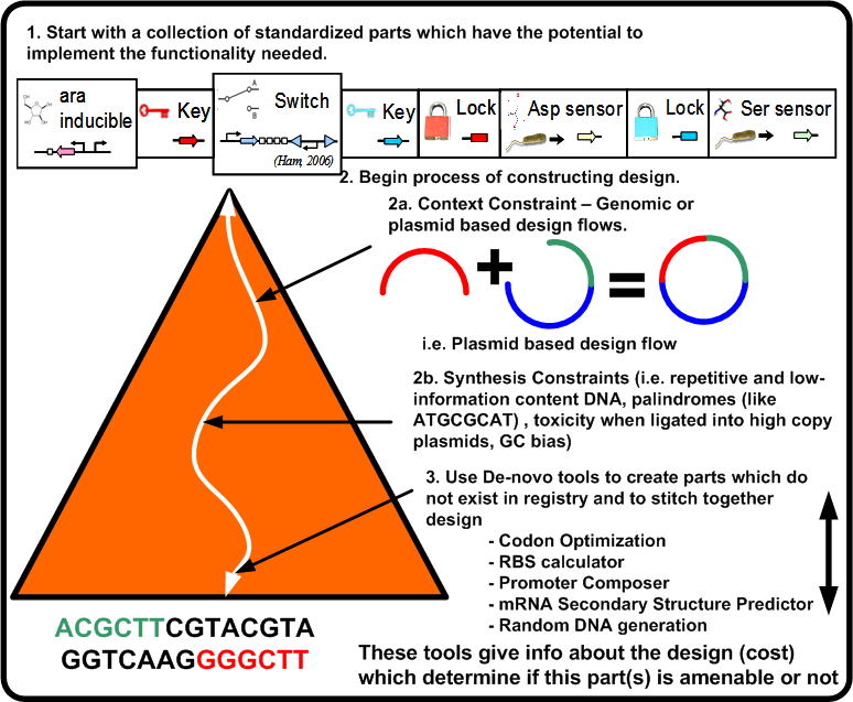
For a synthetic biological system, once the functional pieces have been constrained as shown in Figure 2 what now is required is the actual stitching together of the standardized parts along with synthesizing the needed parts if they do not exist. This leads to the following two points:
- Designs will be composed both of parts which exist in registries as well as DNA synthesized by De-novo tools which fill in the gaps of the design. Parts in registries should be assembled in a standardized way <ref name="BioBricks">T. F. K. Jr. Idempotent vector design for standard assembly of biobricks. Technical report, MIT AI Lab, 2002.</ref>.
- Parts must export up cost metrics to allow the design space exploration process to occur. These costs allow decisions to be made regarding the functional assignment to parts (i.e. mapping).
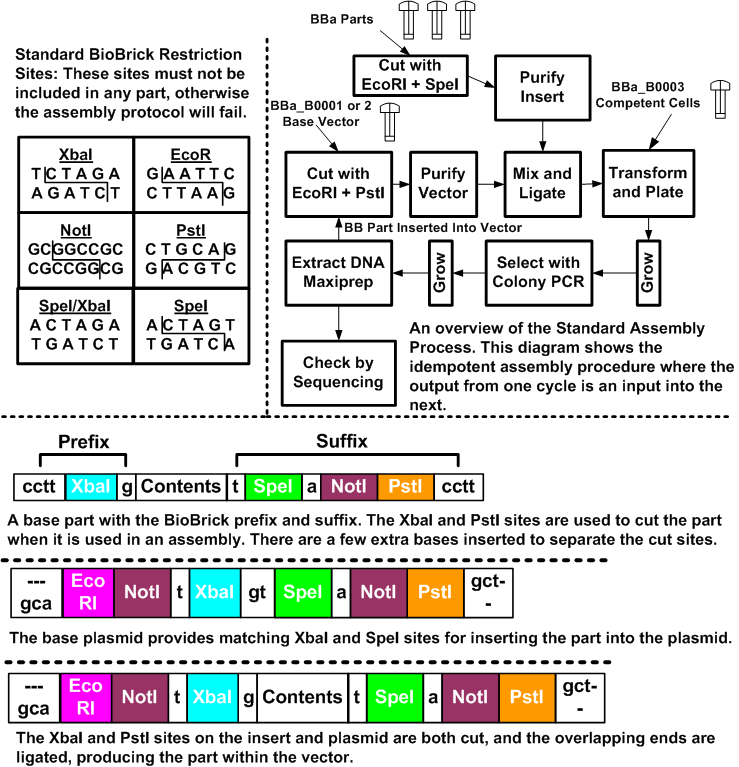
To give an example of such a stiching assembly method, 4 illustrates how this is done for the BioBricks system. The BioBricks parts are comprised of their contents, and standard BioBricks ends. The contents are arbitrary, with the caveat that they may not contain any of the BioBricks restriction sites (EcoRI, XbaI, SpeI, NotI and PstI). These sites can be mutated out through manual edits of the sequence. In most cases, changes can be made that do not affect the system due to the redundancy in the codon specificity. The prefix for a part is a cctt +XbaI + g site, and the suffix is a t + SpeI + a + NotI + PstI + cctt. The restriction sites enable the idempotent construction, while the extra bases help to separate restriction sites and allow the enzymes some overhang at the ends.
Parts are grown and stored in plasmid vectors. These vectors are circular pieces of DNA that bacteria exchange with each other. There is a set of standard BioBrick plasmids that are used to build and grow parts. They contain sites that enable the introduction of the BioBrick parts.
To put parts together, we cut the parts with the appropriate restriction enzymes and then ligate the cut products together. In Figure 4, we place one part on the beginning of another part.
The key to the idempotent assembly process is the convenient nature of the XbaI and SpeI sites. The overhang is identical, but the ends of each cut site are different, so the combined site can be ligated, but not cut. Yet, the ends remain the same, and thus, we can compose parts again and again.
For the component that we are prepending, we take the DNA and cut it with EcoRI, and XbaI. The component we are inserting is cut with EcoRI and SpeI. These components are then ligated together and the result is the combined part, with the same ends, but with an uncuttable mixed SpeI/XbaI site where they were ligated.
Figure 5 illustrates the constraints which take the potential parts of the biological platform for a given functionality and compose them to an actual design instance (DNA sequence). This requires a number of steps in which the design becomes closer to implementation while at the same time updating the overall cost of the design.
Figure 6 illustrates BioJADE's vision of an architectural instance (DNA sequence). There are two panes, the upper pane simply shows the sequence, while the bottom pane provides an annotated view of selected sections.
Mapping
Once the functional description has been constrained and the architecture instance costs determined, the mapping process becomes one of selecting functionality and assigning it the services provided by the architecture instances. This is only possible once those two steps have been done such that both spaces are specified in the same semantic domain <ref name ="commondomain"> \citeQ. Zhu, A. Davare, and A. Sangiovanni-Vincentelli. A semantic-driven synthesis flow for platform-based design. In submitted to Fourth ACM-IEEE International Conference on Formal Methods and Models for Codesign (MEMOCODE’06), July 2006.</ref>. This happens at a variety of abstraction levels. In electronic system design, a more abstract level may include the assignment of services such as execute, read, and write to an ALU and memory interfaces respectively. A lower level of abstraction may assign a 4-input AND operation to either a single 4-input AND gate or to a collection of three 2-input AND gates as a simple two level logic circuit. The selection of a final mapping is based on the resulting costs and the designer's objectives (i.e. the a single 4-input AND may have a smaller area requirement than three 2-input ANDs).
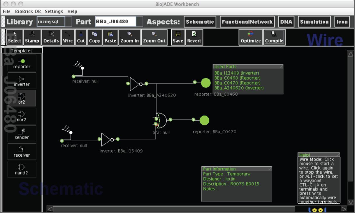
Mapping in synthetic biology is a complex process. Not only does one need to assign functionality to available DNA sequences but the assignment of functionality to a sequence may either preclude or enhance the selection of functionality to other parts available to the design. Specific mappings may create chemicals not present in other mappings, express genes with a higher or lower probability, and react faster or slower in the given environment. A mapping tool should attempt to predict these relationships when possible and highlight parts which make a given mapping more likely to be successful in practice. Figure 7 illustrates mapping issues.
Figure 8 illustrates BioJADE's schematic aspect which is closely tied to the mapping process. Part prototypes can be selected from a library, and wired together to form a gate-level representation of a desired function. Specific implementations of the part prototypes can be selected, or automatically assigned by BioJADE to implement the desired circuitry. This assignment is an example of the mapping process.
Project Architecture
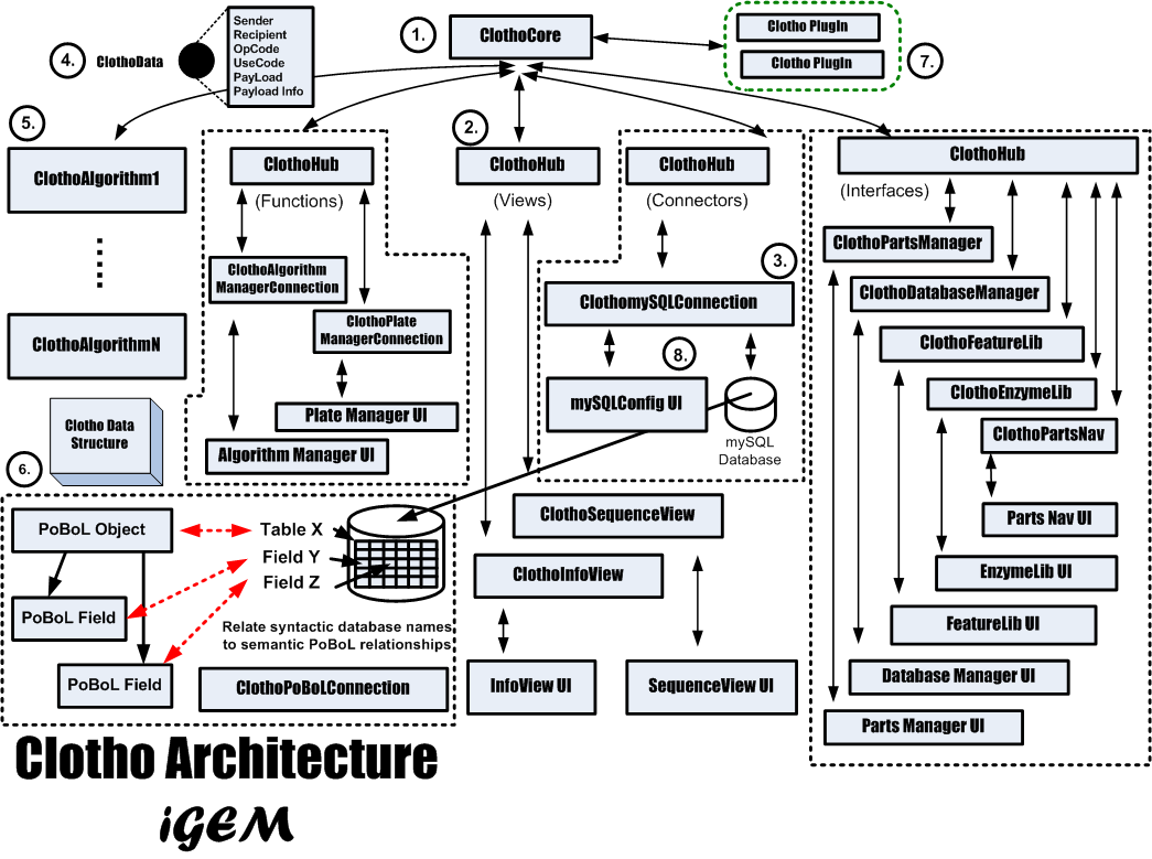
Clotho is based on a core-and-hub system which manages multiple connections, in which each connection serves an independent purpose in a self-sufficient manner. For instance, while one connection may be in charge of viewing/editing a sequence in an ApE-based manner, another connection may connect to databases, and will allow the user to receive and submit parts. Each connection may also perform more integrative tasks by passing data to each other through the core. If a user were working through the sequence view and database manager, for example, then the two connections could talk to each other if the user wished to edit a part in the sequence view and then resubmit the part back to the database.
Clotho's development page provides information on all current viewable connections.
Project Details
Overall Timeline
- iGEM 1st Meeting: June 2, 2008 - Nade and Matt start.
- Anne arrives: June 9th, 2008
- Check-up with Prof. Anderson: June 16, 2008
- iGEM picture session: July 7, 2008
- Clotho Testing Session 1: July 14, 2008
- Clotho Testing Session 2: July 16, 2008
- Clotho Alpha Release: July 26, 2008 - Download Here.
- Anne leaves (and sadness ensues): August 1, 2008
- Clotho Beta Release:
- iGEM 2008 Jamboree:
Getting Acquainted To Clotho
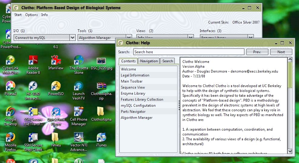
When the user first starts up the .jar file, they will notice that they are first greeted with Clotho's splash screen, and then the Clotho toolbar. The toolbar is the main window that will be used to access all connections from a central interface. Along the top of the toolbar, users can change the skins of the program by accessing Options->Set Skin. Under Info->Help, users can access documentation about various connections.
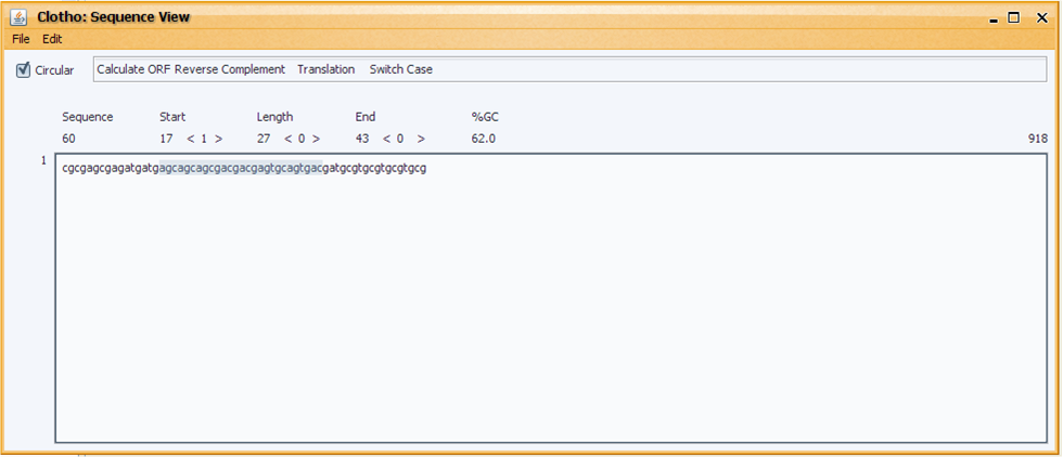
First-time users may be most comfortable with the sequence view before accessing any of the other connections. To access the sequence view, open Views->Sequence View.
Here users may view and edit sequences in the Fasta, Genbank, Strider and ApE formats. More information about the sequence view can be found under the sequence view help article.
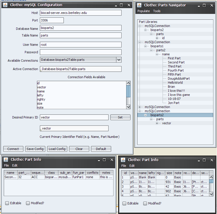
Users should also get acquainted to the Algorithm Manager and mySQL Connections. Return to the toolbar, open I/O->Connect to mySQL.
Here, users can interact with databases and sort through parts organized in mySQL. Once again, more information can be found in the corresponding help article. Also open here is the parts navigator, which is, for the time being, useful insofar as Clotho is connected to a mySQL database.
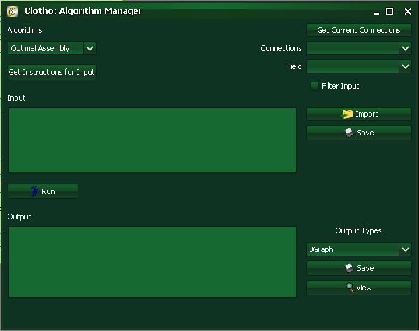
To access the Algorithm Manager Connection open Interfaces->Algorithm Manager.
The algorithm manager allows users tremendous creative control. The algorithm manager can take in an input, and spit out an output depending on the current algorithm implemented. Examples of possible algorithms include optimal assembly algorithms (look at 2ab assembly under the algorithm manager as a concrete example that also considers antibiotics), sequence alignment GUIs, and an icon viewer that takes oligos and visually represents them in a graphical format. The possibilities here are near endless.
The Testing Sessions
Information and pictures regarding the testing sessions can be found here.
The Alpha Release
The Path Forward
Clotho Development
Ongoing development information on Clotho can be found here.
References
<references />
 "
"
