Team:Bologna/Project
From 2008.igem.org
(→Ecoli.PROM: an Erasable and Programmable Genetic Memory in E. coli) |
(→Collaboration with other iGEM2008 Teams) |
||
| (110 intermediate revisions not shown) | |||
| Line 1: | Line 1: | ||
<html> | <html> | ||
<style type="text/css"> | <style type="text/css"> | ||
| - | + | ||
body {background-color:#000000} | body {background-color:#000000} | ||
strong {color: #c09a6d;} | strong {color: #c09a6d;} | ||
| Line 11: | Line 11: | ||
[[Image:Logo1a.gif|220px]][[Image:Testata_dx.jpg|745px]] | [[Image:Logo1a.gif|220px]][[Image:Testata_dx.jpg|745px]] | ||
!align="center"|[[Team:Bologna|HOME]] | !align="center"|[[Team:Bologna|HOME]] | ||
| - | |||
!align="center"|[[Team:Bologna/Project|PROJECT]] | !align="center"|[[Team:Bologna/Project|PROJECT]] | ||
| - | !align="center"|[[Team:Bologna/ | + | !align="center"|[[Team:Bologna/Team|TEAM]] |
| - | + | ||
!align="center"|[[Team:Bologna/Software|SOFTWARE]] | !align="center"|[[Team:Bologna/Software|SOFTWARE]] | ||
| + | !align="center"|[[Team:Bologna/Modeling|MODELING]] | ||
| + | !align="center"|[[Team:Bologna/Wetlab|WET LAB]] | ||
| + | !align="center"|[[Team:Bologna/Notebook|LAB-BOOK]] | ||
!align="center"|[[Team:Bologna/Parts|SUBMITTED PARTS]] | !align="center"|[[Team:Bologna/Parts|SUBMITTED PARTS]] | ||
!align="center"|[[Team:Bologna/Biosafety|BIOSAFETY AND PROTOCOLS]] | !align="center"|[[Team:Bologna/Biosafety|BIOSAFETY AND PROTOCOLS]] | ||
| - | |||
|} | |} | ||
| Line 25: | Line 25: | ||
<div style="text-align:justify"> | <div style="text-align:justify"> | ||
= Ecoli.PROM: an Erasable and Programmable Genetic Memory in ''E. coli''= | = Ecoli.PROM: an Erasable and Programmable Genetic Memory in ''E. coli''= | ||
| - | + | __FORCETOC__ | |
[[Image:Circuito2.jpg|510px|right|thumbnail|Figure 1: Genetic circuit]] | [[Image:Circuito2.jpg|510px|right|thumbnail|Figure 1: Genetic circuit]] | ||
| - | The specific goal of our project was to design a bacterial reprogrammable memory, i.e. colonies of genetically engineered ''E. coli'' immobilized in solid medium where they work as an array of binary memory cells. | + | The specific goal of our project was to design a bacterial reprogrammable memory, i.e. colonies of genetically engineered ''E. coli'' immobilized in solid medium where they work as an array of binary memory cells. To engineer the bacteria we designed a modular genetic [[Team:Bologna/Modeling#SR_Latch|Flip-Flop]] composed of two parts (Figure 1): a binary memory block and an induction block, sensitive to [[Team:Bologna/Wetlab#Uv-Sensitive_Trigger|UVc radiation]]. |
| + | UVc has been chosen to have a fine spatial selectivity in programming the memory cells, whereas IPTG should be used to reset the entire memory. | ||
| - | + | The molecular circuit can switch between two different stable states (LacI-ON and TetR-ON), driven by the external stimuli UVc and IPTG. LacI-ON represents the stable state in which LacI gene is active and LacI protein represses the TetR gene expression, with a positive feedback. Therefore, the LacI-ON state coincides with the TetR-OFF condition. On the contrary, the TetR-ON represents the state with the TetR gene active and the LacI gene silenced (LacI-OFF). Owing to the coexistence of two stable states (bistability), this circuit is capable of serving as a binary memory. We denominated it genetic Flip-Flop since it works as a SR Latch: LacI state is the [[Image:q.jpg]] output and TetR state is the [[Image:qneg.jpg]] output. Uvc is the set signal and IPTG is the reset signal. Indeed, IPTG stimulation inhibits LacI repressor, thus can cause the transition from the LacI-ON state to the TetR-ON. UVc radiation, inactivating LexA repressor through the [[Team:Bologna/Modeling#UV_Radiation:_SOS_system|SOS response]] [Friedberg et al. 1995] can cause the opposite transition from LacI-ON to TetR-ON. | |
| - | The core elements of | + | The core elements of this epigenetic memory are the two mutually regulated promoters (see Figure 1), each designed as a constitutive promoter flanking an indipendent operator site. In this way, the promoter transcriptional strength and the repressor binding affinity can be independently fixed. [[Team:Bologna/Modeling#Mathematical_Model|Mathematical model analysis and computer simulations]] were used to obtain a rational design of the regulated promoters. By the model we found the analytic relationships to quote the regulated promoter in terms of transcriptional strength and sensitivity to the repressor and we established such a relevant circuit properties as the bistability and the [[Team:Bologna/Modeling#Numerical_simulations|dynamical response to inputs]]. |
| - | + | <br> | |
| + | [[Image:Rangeofbistability2.jpg|500 px|center|thumbnail|Figure 2. Range of bistability for the genetic Flip-Flop]] | ||
| - | + | <br> | |
| - | + | As shown in Figure 2, the coexistence of two stable equilibria (LacI-ON and TerR-ON) is guaranteed for[[image:ki.jpg]]and [[image:kr.jpg]]model parameters greater than 3 in a large range of values (bistability range). To have a good robustness we fixed [[image:ki.jpg]] and [[image:kr.jpg]] equal to 10. For this value the circuit is sufficently distant from the bifurcation lines to avoid random memory switching but it is possible to set (or to reset) the memory with proper [[Team:Bologna/Modeling#Numerical_simulations|UV and IPTG stimulations]]. | |
| - | + | Since the Registry lacks promoters with the K-parameter equal to 10, we decided to introduce operator site parts in order to build regulated promoter with the fixed transcriptional strenght and repression sensitivity. | |
| + | Thus, we synthesized four libraries of operator sequences, respectively for [http://partsregistry.org/wiki/index.php?title=Part:BBa_K079045 LacI], [http://partsregistry.org/wiki/index.php?title=Part:BBa_K079046 TetR], [http://partsregistry.org/wiki/index.php?title=Part:BBa_K079047 cI] and [http://partsregistry.org/wiki/index.php?title=Part:BBa_K079048 LexA] repressor proteins ([http://partsregistry.org/wiki/index.php?title=Part:BBa_K079045 see details]). In each library, there are three sequences each with a different repressor [[Team:Bologna/Wetlab#At_last..._Operator_sites_as_BioBricks.21|binding affinity]] to the repressor protein. We isolated each operator with the intention to clone them into BioBrick standard assembly plasmids. | ||
| - | + | We assessed the functionality of independent operators by assembling one circuit (Figure 3, closed-loop configuration) where the constitutive promoter BBa_J23118 and LacI operator 2 were auto-regulated by the LacI repressor. GFP was used as the reporter. An identical construct without the LacI operator site was used as the negative control (Figure 3, open-loop configuration). | |
| - | + | <br> | |
| - | + | [[Image:bba020.jpg|center|thumbnail|400 px|Figure 3. Upper panel: Closed-loop configuration (K079020); lower panel Open-loop configuration (K079026)]] | |
| + | <br> | ||
| + | Fluorescence images below demonstrate the repression due to the presence of the Lac operator. | ||
| - | < | + | <br> |
| - | + | ||
| - | + | ||
| - | + | ||
| - | + | ||
| - | [ | + | {|align="center" |
| + | |[[Image:closed.jpg|thumbnail|350 px|Figure 4a. Open-Loop configuration (K079026)]] | ||
| + | |[[Image:open.jpg|thumbnail|350 px|Figure 4b. Closed-Loop configuration (K079020)]] | ||
| + | |} | ||
| - | + | <br> | |
| - | + | Analisys of single bacteria fluorescence (Figure 5) confirmed the significative repression (116±29 vs. 38±12). | |
| + | K parameter determined by these constructs was about 4. | ||
| + | <br> | ||
| - | [ | + | [[Image:Box.jpg|thumbnail|center|500 px|Figure 5. Box Plot of bacterium fluorescence (n=683). Max and minimum values are indicated by the horizontal bars. The median and lower and upper quartiles are also indicated.]] |
| - | + | <br> | |
| - | + | In the genetic Flip-Flop, the amount of LacI to set ON the memory is induced by an UV-sensitive trigger. To test the lexA operator functionality, we assembled the BBa_K079050 construct (Figure 6). | |
| - | + | ||
<br> | <br> | ||
| - | |||
| - | + | [[Image:fig050.jpg|center|thumbnail|388 px| Figure 6. K079050 GFP reporter protein under the control of the J23100 constitutive promoter and LexA 2 operator ]] | |
| - | + | <br> | |
| + | |||
| + | Since we have not success with UV induction, we tested the correct functionality of K079050 by hydrogen peroxide induction. As it can be seen in Figure 7a, the presence of the lexA operator 2 repressed the GFP synthesis. As expected, the hydrogen peroxide, when added, inhibited the lexA repressor activity and induced GFP synthesis. | ||
| + | |||
| + | <br> | ||
| + | |||
| + | {|align="center" | ||
| + | |[[Image:immag5.jpg|center|thumbnail|300 px|Figure 7a. K079050 without H2O2]] | ||
| + | |[[Image:imm4.jpg|center|thumbnail|300 px|Figure 7b. K079050 with H2O2]] | ||
| + | |} | ||
| + | |||
| + | <br> | ||
| + | |||
| + | Our results on the use of operator sequences, as independent parts in the assembling of regulated promoters, are still preliminary. However, we are confident that these parts can give a fine-tuning of promoter sensitivity to the repressor allowing the rational design of regulation promoters for Synthetic Biology. | ||
[https://2008.igem.org/Team:Bologna/Project ''Up''] | [https://2008.igem.org/Team:Bologna/Project ''Up''] | ||
| - | = | + | =Collaboration with other iGEM 2008 Teams = |
| + | |||
| + | * After the last year competition, at the beginning of the 2008, we decided to get a new team started for iGEM2008 competition. In April, we got in contact with Prof. Paolo Magni, who wanted to start a new team in [[Team:UNIPV-Pavia|Pavia]] for iGEM2008. So, in order to share experiences and ideas about iGEM, and to show him what kind of wet lab resources are necessary to develop a Synthetic Biology project, we met at the Cellular and Molecular Engineering Laboratory of the University of Bologna- Cesena Campus. After this first meeting, there have been other chances to meet during the summer. In particular, several conference calls were organized and two meetings were scheduled in Pisa and Bressanone (Italy). It was fundamental to compare lab protocols and techniques to help each other avoiding mistakes and speeding up project progress. The main topics of our discussion were the optimization of plasmid resuspension and ligation reaction steps as well as how to measure fluorescence. Finally, before DNA Repository quality control publication on the Registry web site, we cross-checked some parts that showed problems after DNA transformation. Problems had been confirmed by quality control results (parts' sequences classified as "inconsistent"). | ||
| + | * We want even to mention the courtesy of the [[Team:Valencia|Valencia]] iGEM Team, that have advised us about the critical use of GFP and RFP at the same time. | ||
| + | |||
| + | |||
| + | [https://2008.igem.org/Team:Bologna/Project ''Up''] | ||
= Concluding the iGEM 2007 Project = | = Concluding the iGEM 2007 Project = | ||
| - | In the iGEM 2007 we used the LacY gene (BBa_J2210) to design | + | In the iGEM 2007 we used the LacY gene (BBa_J2210) to design a genetic Schmitt trigger. Since this part was not working well, we sent it to be sequenced and found that it contained a 35 bp insertion upstream the endogenous LacY gene sequence. This insertion probably caused a frameshift in protein translation, making the gene ineffective. So, we amplified the right gene sequence and put it in the BioBrick format. Successive sequencing confirmed the right assembling of this part. We also measured IPTG-induced fluorescence in the genetic Schmitt trigger (see Figure 8) and we assessed the correct function of the new LacY part. To contribute to Registry’s improvement we decided to send this new part to the Registry ([http://partsregistry.org/Part:BBa_K079015 K0790015]). |
| + | |||
| + | <br> | ||
| - | [[Image:Progetto.jpg|center|thumbnail|500 px|Schematic representation of the genetic Schmitt Trigger. The LacI generator module was included to have a constitutive synthesis of LacI repressor protein witch makes up for endogenous LacI. LacY permease introduces a positive feedback. GFP is the reporter for pLac activation. This circuit express high level of fluorescence with very low concentration of inducer (IPTG=1uM). After switching, the fluorescence level f is insensitive to | + | [[Image:Progetto.jpg|center|thumbnail|500 px|Figure 8. Schematic representation of the genetic Schmitt Trigger. The LacI generator module was included to have a constitutive synthesis of LacI repressor protein witch makes up for endogenous LacI. LacY permease introduces a positive feedback. GFP is the reporter for pLac activation. This circuit express high level of fluorescence with very low concentration of inducer (IPTG=1uM). After switching, the fluorescence level f is insensitive to an increase in inducer dosage.]] |
[https://2008.igem.org/Team:Bologna/Project ''Up''] | [https://2008.igem.org/Team:Bologna/Project ''Up''] | ||
Latest revision as of 16:52, 20 November 2008
| HOME | PROJECT | TEAM | SOFTWARE | MODELING | WET LAB | LAB-BOOK | SUBMITTED PARTS | BIOSAFETY AND PROTOCOLS |
|---|
Contents |
Ecoli.PROM: an Erasable and Programmable Genetic Memory in E. coli
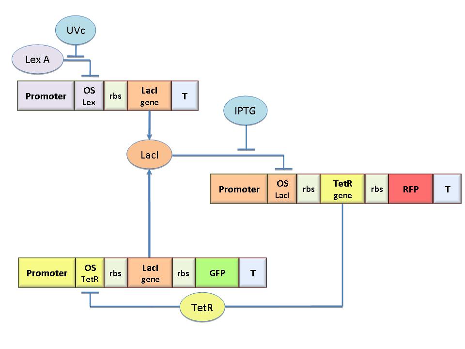
The specific goal of our project was to design a bacterial reprogrammable memory, i.e. colonies of genetically engineered E. coli immobilized in solid medium where they work as an array of binary memory cells. To engineer the bacteria we designed a modular genetic Flip-Flop composed of two parts (Figure 1): a binary memory block and an induction block, sensitive to UVc radiation. UVc has been chosen to have a fine spatial selectivity in programming the memory cells, whereas IPTG should be used to reset the entire memory.
The molecular circuit can switch between two different stable states (LacI-ON and TetR-ON), driven by the external stimuli UVc and IPTG. LacI-ON represents the stable state in which LacI gene is active and LacI protein represses the TetR gene expression, with a positive feedback. Therefore, the LacI-ON state coincides with the TetR-OFF condition. On the contrary, the TetR-ON represents the state with the TetR gene active and the LacI gene silenced (LacI-OFF). Owing to the coexistence of two stable states (bistability), this circuit is capable of serving as a binary memory. We denominated it genetic Flip-Flop since it works as a SR Latch: LacI state is the ![]() output and TetR state is the
output and TetR state is the ![]() output. Uvc is the set signal and IPTG is the reset signal. Indeed, IPTG stimulation inhibits LacI repressor, thus can cause the transition from the LacI-ON state to the TetR-ON. UVc radiation, inactivating LexA repressor through the SOS response [Friedberg et al. 1995] can cause the opposite transition from LacI-ON to TetR-ON.
output. Uvc is the set signal and IPTG is the reset signal. Indeed, IPTG stimulation inhibits LacI repressor, thus can cause the transition from the LacI-ON state to the TetR-ON. UVc radiation, inactivating LexA repressor through the SOS response [Friedberg et al. 1995] can cause the opposite transition from LacI-ON to TetR-ON.
The core elements of this epigenetic memory are the two mutually regulated promoters (see Figure 1), each designed as a constitutive promoter flanking an indipendent operator site. In this way, the promoter transcriptional strength and the repressor binding affinity can be independently fixed. Mathematical model analysis and computer simulations were used to obtain a rational design of the regulated promoters. By the model we found the analytic relationships to quote the regulated promoter in terms of transcriptional strength and sensitivity to the repressor and we established such a relevant circuit properties as the bistability and the dynamical response to inputs.
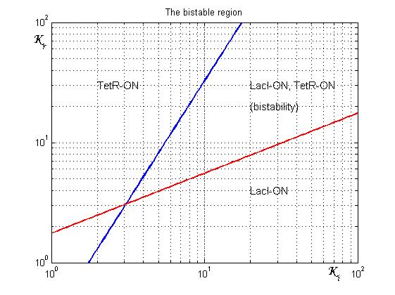
As shown in Figure 2, the coexistence of two stable equilibria (LacI-ON and TerR-ON) is guaranteed for![]() and
and ![]() model parameters greater than 3 in a large range of values (bistability range). To have a good robustness we fixed
model parameters greater than 3 in a large range of values (bistability range). To have a good robustness we fixed ![]() and
and ![]() equal to 10. For this value the circuit is sufficently distant from the bifurcation lines to avoid random memory switching but it is possible to set (or to reset) the memory with proper UV and IPTG stimulations.
equal to 10. For this value the circuit is sufficently distant from the bifurcation lines to avoid random memory switching but it is possible to set (or to reset) the memory with proper UV and IPTG stimulations.
Since the Registry lacks promoters with the K-parameter equal to 10, we decided to introduce operator site parts in order to build regulated promoter with the fixed transcriptional strenght and repression sensitivity. Thus, we synthesized four libraries of operator sequences, respectively for [http://partsregistry.org/wiki/index.php?title=Part:BBa_K079045 LacI], [http://partsregistry.org/wiki/index.php?title=Part:BBa_K079046 TetR], [http://partsregistry.org/wiki/index.php?title=Part:BBa_K079047 cI] and [http://partsregistry.org/wiki/index.php?title=Part:BBa_K079048 LexA] repressor proteins ([http://partsregistry.org/wiki/index.php?title=Part:BBa_K079045 see details]). In each library, there are three sequences each with a different repressor binding affinity to the repressor protein. We isolated each operator with the intention to clone them into BioBrick standard assembly plasmids.
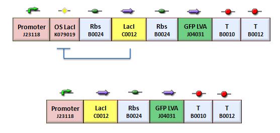
We assessed the functionality of independent operators by assembling one circuit (Figure 3, closed-loop configuration) where the constitutive promoter BBa_J23118 and LacI operator 2 were auto-regulated by the LacI repressor. GFP was used as the reporter. An identical construct without the LacI operator site was used as the negative control (Figure 3, open-loop configuration).
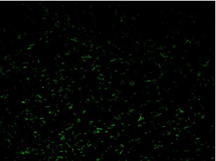
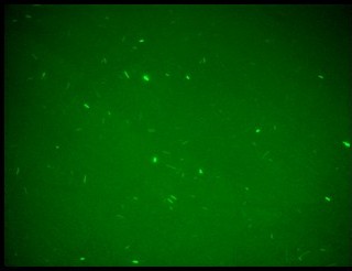
Fluorescence images below demonstrate the repression due to the presence of the Lac operator.
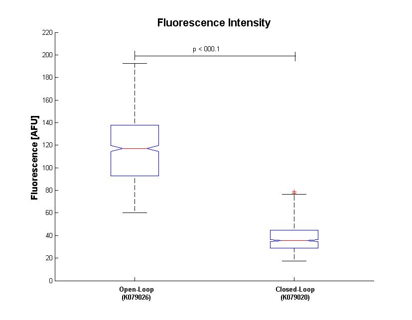
Analisys of single bacteria fluorescence (Figure 5) confirmed the significative repression (116±29 vs. 38±12). K parameter determined by these constructs was about 4.
In the genetic Flip-Flop, the amount of LacI to set ON the memory is induced by an UV-sensitive trigger. To test the lexA operator functionality, we assembled the BBa_K079050 construct (Figure 6).
Since we have not success with UV induction, we tested the correct functionality of K079050 by hydrogen peroxide induction. As it can be seen in Figure 7a, the presence of the lexA operator 2 repressed the GFP synthesis. As expected, the hydrogen peroxide, when added, inhibited the lexA repressor activity and induced GFP synthesis.
Our results on the use of operator sequences, as independent parts in the assembling of regulated promoters, are still preliminary. However, we are confident that these parts can give a fine-tuning of promoter sensitivity to the repressor allowing the rational design of regulation promoters for Synthetic Biology.
Collaboration with other iGEM 2008 Teams
- After the last year competition, at the beginning of the 2008, we decided to get a new team started for iGEM2008 competition. In April, we got in contact with Prof. Paolo Magni, who wanted to start a new team in Pavia for iGEM2008. So, in order to share experiences and ideas about iGEM, and to show him what kind of wet lab resources are necessary to develop a Synthetic Biology project, we met at the Cellular and Molecular Engineering Laboratory of the University of Bologna- Cesena Campus. After this first meeting, there have been other chances to meet during the summer. In particular, several conference calls were organized and two meetings were scheduled in Pisa and Bressanone (Italy). It was fundamental to compare lab protocols and techniques to help each other avoiding mistakes and speeding up project progress. The main topics of our discussion were the optimization of plasmid resuspension and ligation reaction steps as well as how to measure fluorescence. Finally, before DNA Repository quality control publication on the Registry web site, we cross-checked some parts that showed problems after DNA transformation. Problems had been confirmed by quality control results (parts' sequences classified as "inconsistent").
- We want even to mention the courtesy of the Valencia iGEM Team, that have advised us about the critical use of GFP and RFP at the same time.
Concluding the iGEM 2007 Project
In the iGEM 2007 we used the LacY gene (BBa_J2210) to design a genetic Schmitt trigger. Since this part was not working well, we sent it to be sequenced and found that it contained a 35 bp insertion upstream the endogenous LacY gene sequence. This insertion probably caused a frameshift in protein translation, making the gene ineffective. So, we amplified the right gene sequence and put it in the BioBrick format. Successive sequencing confirmed the right assembling of this part. We also measured IPTG-induced fluorescence in the genetic Schmitt trigger (see Figure 8) and we assessed the correct function of the new LacY part. To contribute to Registry’s improvement we decided to send this new part to the Registry ([http://partsregistry.org/Part:BBa_K079015 K0790015]).

 "
"
