Team:Paris/Analysis
From 2008.igem.org
| Line 1: | Line 1: | ||
{{Paris/Menu}} | {{Paris/Menu}} | ||
{{Paris/Header|Network Analysis}} | {{Paris/Header|Network Analysis}} | ||
| - | |||
| - | |||
| - | |||
| - | |||
| - | |||
| - | |||
| - | |||
| - | |||
| - | |||
| - | |||
| - | |||
This page presents the principal analytic results derived from the models, corresponding to the [[Team:Paris/Analysis/Design3|genetic networks]] we have designed (FIFO, oscillations, ...), as well as representative simulations' results. | This page presents the principal analytic results derived from the models, corresponding to the [[Team:Paris/Analysis/Design3|genetic networks]] we have designed (FIFO, oscillations, ...), as well as representative simulations' results. | ||
Revision as of 00:31, 30 October 2008
|
Network Analysis
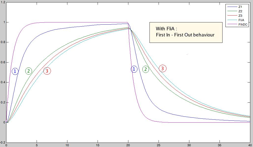
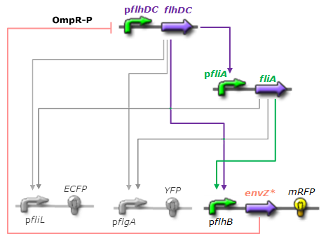
This page presents the principal analytic results derived from the models, corresponding to the genetic networks we have designed (FIFO, oscillations, ...), as well as representative simulations' results. This has led us to propose some modifications of the initial system, in order to obtain an improved oscillating system. FIFO behaviourHere are the network and simulations corresponding to the FIFO aspect : As explained here, the FIFO circuit is made of a main regulator (FlhDC) that activates an intermediary regulator (FliA) and the three output genes Z1, Z2, and Z3 that are activated by the combined effect of the two regulators.
The simulation on the right, based on parameter values found in [http://www.ncbi.nlm.nih.gov/pubmed/16729041?ordinalpos=1&itool=EntrezSystem2.PEntrez.Pubmed.Pubmed_ResultsPanel.Pubmed_DefaultReportPanel.Pubmed_RVDocSum Shiraz Kalir et al. (2004)] directly repoduced a FIFO behaviour: the output genes are inactivated in the same order they are activated. Go further into OscillationsThe first attempt for an oscillation circuit is implemented as a simple negative feedback loop connecting one output of the FIFO circuit to the input regulator :
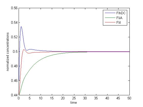
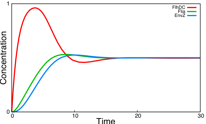
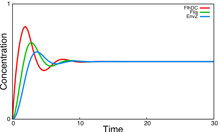
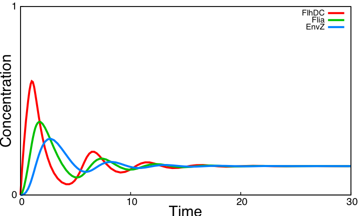
From the simulations performed with parameters found in the literature, we conclude that the system reaches a steady state and is far from oscillating ! We evaluate the role of key interactions of the core system by successively simulating altered forms of the system. Curves below display simulations of 3 simple variants of the model, none of which producing sustained oscillations. Moreover, a mathematical analysis confirms that the core system cannot produce oscillations. These three alternatives are implemented using the programming environment for modeling biochemical systems [http://contraintes.inria.fr/BIOCHAM/ BIOCHAM] (see code).
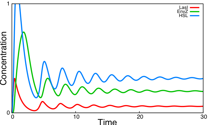
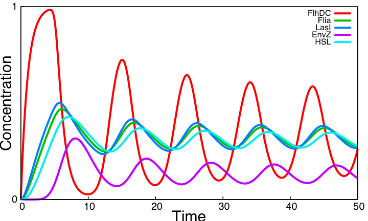
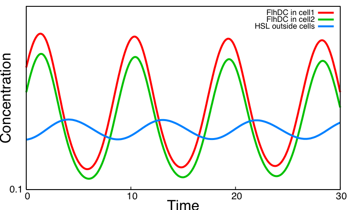
System ImprovementsOur aim is to explore improvements of the core system providing both sustained oscillations and synchronization capabilities. We consider two systems based on quorum sensing thus adding at the same time a delay valuable for the oscillations and the ability to synchronize cells via HSL concentration in the environment. The first system is inspired by [2] and is made of two coupled negative loops. The second one is a rewiring of the core system to include quorum sensing and resulting in a single negative loop. Simulation results point out that only this second system delivers sustained oscillations. Moreover we confirm that quorum sensing can indeed be used to synchronize a population of cells.
|
 "
"


