Team:KULeuven/Model/Output
From 2008.igem.org
(→Sensitivity Analysis) |
m (→Parameters) |
||
| Line 59: | Line 59: | ||
|- | |- | ||
| k<sub>CFP</sub> | | k<sub>CFP</sub> | ||
| - | | 0. | + | | 0.167 s<sup>-1</sup> |
| RBS is B0032 (efficiency of 0.3) | | RBS is B0032 (efficiency of 0.3) | ||
| | | | ||
Revision as of 09:18, 11 August 2008
Contents |
Output
Position in the system
The output system is one of three modules directly linked to the output of the light sensor (black-box) the input for is OmpF. The output system is a simple gene regulation, of which transcription is activated by OmpF. The output signal is CFP (cyan fluorescent protein).
In the applied project of dealing with Crohn's disease this would be replaced by the drug necessary to cure the local inflammation. The drug concentration would be proportional to the amount of local inflammation sensed.
Describing the system
ODE's
Parameters
| Name | Value | Comments | Reference |
|---|---|---|---|
| Degradation Rates | |||
| dCFP (protein) | 1.05E-4 s-1 | [http://parts.mit.edu/igem07/index.php/ETHZ/Parameters link] | |
| dRNA_CFP (mRNA) | 0.0023 s-1 | [http://www.pubmedcentral.nih.gov/picrender.fcgi?artid=124983&blobtype=pdf link] | |
| Transcription Rates | |||
| kCFP | OmpF dependent | ||
| Translation Rates | |||
| kCFP | 0.167 s-1 | RBS is B0032 (efficiency of 0.3) | |
Models
CellDesigner (SBML file)
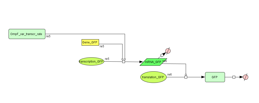
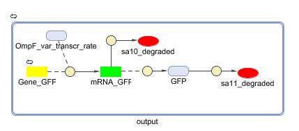
The Output model represented in CellDesigner:
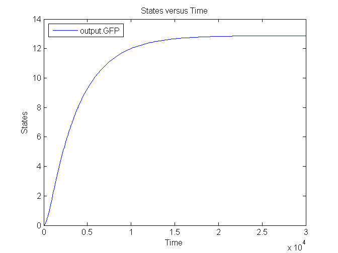
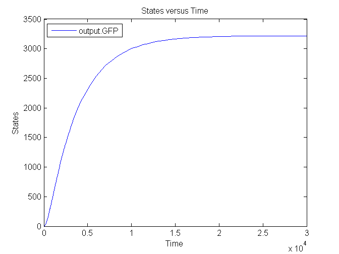
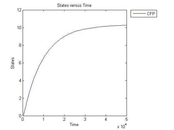
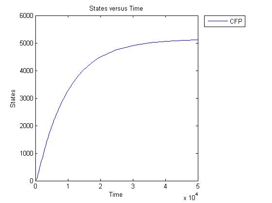
Several simulations were conducted, the following two show the transient respons and eventual saturation of the output system to a low and a high step signal as input, respectively. We see that there is a great distinction in the number of CFP molecules between the two input signals.
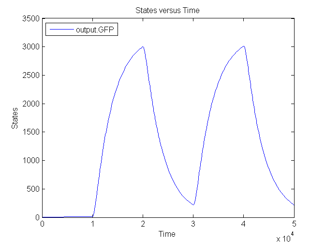
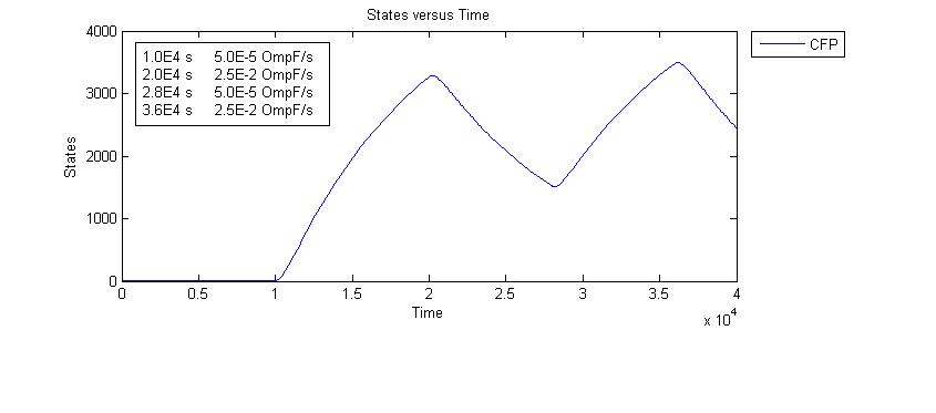
Next figure shows the switching behaviour of the output system to an light signal turning off and on:
Matlab (SBML file)
The diagram for the output system is shown below:
Another two simulations have been conducted, matching the solutions found by CellDesigner, the low input respons (0.0005 OmpF s-1) is on the left, the high input respons (0.025 OmpF s-1) on the right:
Next figure demonstrates the switching behaviour and concides with the results predicted by CellDesigner:
 "
"


