Team:Bologna/Wetlab
From 2008.igem.org
(→At last... Operator sites as BioBricks!) |
(→UV Induction) |
||
| Line 162: | Line 162: | ||
Tests with difference distances from the lamp (3 and 4 cm) with different exposition times (1, 10 and 15 s) were done. Minimum distance and maximum time were fixed to avoid lethal UV dose and mutagenesis.<br> | Tests with difference distances from the lamp (3 and 4 cm) with different exposition times (1, 10 and 15 s) were done. Minimum distance and maximum time were fixed to avoid lethal UV dose and mutagenesis.<br> | ||
| - | After induction by UV the samples were kept for 2 hours in dark by silver paper to increase the RecA and LexA response. The OD was measured and the sample transferred in a 1ml tube, spinned at 6000-8000rpm for three minutes, the supernatant was harvested and the pellet resuspended. Slides were prepared for the fluorescence bacteria image acquisition that were elaborated with the Visual Fluo Bacteria Software . | + | After induction by UV the samples were kept for 2 hours in dark by silver paper to increase the RecA and LexA response. The OD was measured and the sample transferred in a 1ml tube, spinned at 6000-8000rpm for three minutes, the supernatant was harvested and the pellet resuspended. Slides were prepared for the fluorescence bacteria image acquisition that were elaborated with the [https://2008.igem.org/Team:Bologna/Software#Visual_Fluo_Bacteria:_a_software_for_the_analysis_of_fluorescence_bacteria_image Visual Fluo Bacteria Software]. |
Unfortunately, using 15ml tube and maybe the not the correct time/distance induction, the experimental tests didn’t shown GFP expression. It could be depended because of not uniform irradiation of the sample. In the Fig. is possible to see a picture of leak answer by bacteria stimulated by UV at the distance of 4cm using less than one second time as exposure. | Unfortunately, using 15ml tube and maybe the not the correct time/distance induction, the experimental tests didn’t shown GFP expression. It could be depended because of not uniform irradiation of the sample. In the Fig. is possible to see a picture of leak answer by bacteria stimulated by UV at the distance of 4cm using less than one second time as exposure. | ||
Revision as of 22:20, 29 October 2008
| HOME | PROJECT | TEAM | SOFTWARE | MODELING | WET LAB | LAB-BOOK | SUBMITTED PARTS | BIOSAFETY AND PROTOCOLS |
|---|
Contents |
Introduction
To obtain regulated promoters we synthesized four libraries of operator sequences, respectively for LacI, TetR, cI and LexA repressor proteins. Here is explained how we designed the operator libraries and isolated single operators to clone them in the standard format. Moreover, we built and tested: a LacI regulated promoter to tune promoter activation and a lexA based promoter to study the SOS activation (UV and peroxidase).
At last... Operator sites as BioBricks!
Even though transcriptional regulation still plays a pivotal role in synthetic biology, a modular assembly of regulated promoters and the characterization of their properties has not been formalized, yet. At present state, each promoter in the Registry, though complex, is treated as a “standalone” monolithic element. Thus, the choice of a regulated promoter implies a prefixed sigmoid regulation curve. The only option, using the current BioBricks, is to choose a discretional scaling factor in the transfer of the transcription function to the protein through an appropriate RBS. Critically, the choice of one specific transcription factor limits the choice to just one possible promoter. The assembly of regulated promoters as the combination of modular parts, i. e. unregulated promoters and operators, could permit the rapid design of regulatory elements with fixed characteristics. In fact, promoter transcriptional strength and repressor binding affinity could be independently chosen.
A first step in the rationalization of promoter design was done in the iGEM 2007 with the introduction in the Registry of a family of constitutive promoters. Each family element differs from the others just for few base pairs in -35 and -10 regions, keeping constant the rest of the sequence and giving rise to a different level of transcription strength. We decided to use this valuable work as a platform for a deeper and more general promoter design strategy. To obtain regulated promoters we decided to combine these parts with short regulatory sequences that operate as a binding site for the transcription factor. To this aim, we synthesized four libraries of operator sequences, respectively for [http://partsregistry.org/wiki/index.php?title=Part:BBa_K079045 LacI], [http://partsregistry.org/wiki/index.php?title=Part:BBa_K079046 TetR], [http://partsregistry.org/wiki/index.php?title=Part:BBa_K079047 cI] and [http://partsregistry.org/wiki/index.php?title=Part:BBa_K079048 LexA] repressor proteins ([http://partsregistry.org/wiki/index.php?title=Part:BBa_K079045 see details]). In each library, there are three sequences (see Table below) each with a different repressor binding affinity to the repressor protein. Since the libraries were synthetized on pGA18 and pMA Geneart vectors, we isolated each operator with the intention to clone them into BioBrick standard assembly plasmids. The choice of the operator should give a relative fine-tuning of promoter sensitivity to the repressor. We decided to take the Berkley's costitutive promoter library as a good "collection" from which we could select the unregulated promoter, according with the chosen transcriptional strength.
| LacI | ||
| Name | Sequence | Affinity |
| [http://partsregistry.org/Part:BBa_K079017 Lac SymL] | aattgtgagcgctcacaatt | Very Strong |
| [http://partsregistry.org/Part:BBa_K079018 Lac O1] | aattgtgagcggataacaatt | Intermediate |
| [http://partsregistry.org/Part:BBa_K079019 Lac O2] | aaatgtgagcgagtaacaacc | Weak |
| Tet | ||
| Name | Sequence | Affinity |
| [http://partsregistry.org/Part:BBa_K079036 TeT O] | cctatcagtgataga | Strong |
| [http://partsregistry.org/Part:BBa_K079037 TetO-4C] | cctgtcagtgacaga | Intermediate |
| [http://partsregistry.org/Part:BBa_K079038 TetO-wt/4C5G] | cctatcagtgacgga | Weak |
| Lambda | ||
| Name | Sequence | Affinity |
| [http://partsregistry.org/Part:BBa_K079041 Lambda OR1] | tatcaccgccagaggta | Strong/Intermediate cI/Cro |
| [http://partsregistry.org/Part:BBa_K079042 Lambda OR2] | taacaccgtgcgtgttg | Intermediate/Weak cI/Cro |
| [http://partsregistry.org/Part:BBa_K079043 Lambda OR3] | tatcaccgcaagggata | Intermediate/Intermediate cI/Cro |
| Lex | ||
| Name | Sequence | Affinity |
| [http://partsregistry.org/Part:BBa_K079039 LexA 1] | atatatatatattcgcgctcgata | Very Strong |
| [http://partsregistry.org/Part:BBa_K079040 LexA 2] | ctgtatgagcatacag | Quite Weak |
Single operators or a combination of them, can be also assembled upstream or downstream with respect to a constitutive promoter. Since, it is known (Cox et al, 2007) that the position of an operator site plays a crucial role in determining repression effects (i. e. [http://partsregistry.org/wiki/index.php?title=Part:BBa_K079041 lambda operators]).
Operator site cloning in standard plasmids
Operator sites are Dna sequences very small in length (15 to 20 bp) and a restriction digestion for the religation in standard plasmids is not possible with the existing purification kits. In fact, only Dna sequences down to at least 40 bp can be efficiently purified with the standard kits available. Small bands extraction requires laborious condition optimization and hazardous reagents like phenol-chloroform So, we decided to set a new protocol up for the isolation and cloning of single operator sites into standard BioBricks plasmids.
We started from the analysis of an existing custom vector into the [http://partsregistry.org/wiki/index.php?title=Part:BBa_J23100 Registry]. In this vector, a RFP gene was cloned, as a reporter, between the SpeI and PstI restriction sites. Thus, this is the only part in the Registry that can be separated from a plasmid with a S/P digestion.
Therefore, once the RFP is isolated with S/P, it could be assembled with an operator sequence digested SpeI- PstI, too. This could allow the isolation of the Operator- RFP sequence from the commercial plasmid and the subsequent religation into a standard plasmid. Then, a final extraction of the RFP gene with a SpeI- PstI digestion would leave the operator site inside the standard plasmid.
Uv Sensitive Trigger
In the genetic flip-flop, the amount of LacI to set ON the memory is induced by an UV-sensitive trigger . Production of LacI molecules by UV induction can be tested by replacing the LacI gene with GFP in the UV trigger, so it is possible to have a relation of the strength of LacI synthesis measuring the value of fluorescence.
We realized two new constructs( K079049 and K079050) to test the UV induction. We used two different promoters(J23118 with 1429 strength and J23100 with 2547 strength). These UV test circuits are presented schematically in Figure 1-2.
To test the UV induction we used the UV illuminator.
UV Induction
Plasmids with the K079049 and K079050 constructs have been transformed in DH5alfa bacteria by standard protocol and one colony from the plate was picked up and cultured overnight in 5ml LB medium broth with ampicillin. The day after the culture was diluted in 5ml LB and antibiotic in order to have OD = 0.1 and let it grown for another one hour; after that the culture was divided in five 15ml tubes (1ml of bacteria per tube).
The 1ml volume was used ti have a layer of medium enough ehin to perform an uniform irradiation.
Tests with difference distances from the lamp (3 and 4 cm) with different exposition times (1, 10 and 15 s) were done. Minimum distance and maximum time were fixed to avoid lethal UV dose and mutagenesis.
After induction by UV the samples were kept for 2 hours in dark by silver paper to increase the RecA and LexA response. The OD was measured and the sample transferred in a 1ml tube, spinned at 6000-8000rpm for three minutes, the supernatant was harvested and the pellet resuspended. Slides were prepared for the fluorescence bacteria image acquisition that were elaborated with the Visual Fluo Bacteria Software.
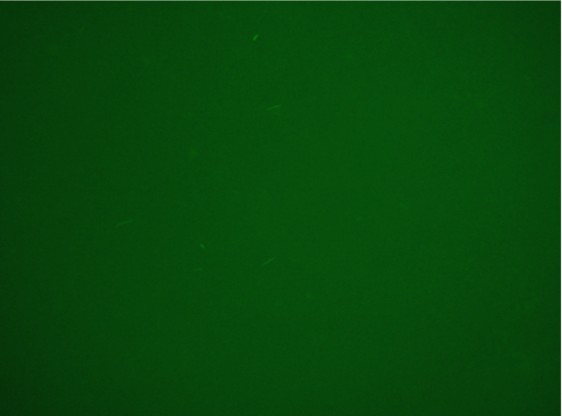
Unfortunately, using 15ml tube and maybe the not the correct time/distance induction, the experimental tests didn’t shown GFP expression. It could be depended because of not uniform irradiation of the sample. In the Fig. is possible to see a picture of leak answer by bacteria stimulated by UV at the distance of 4cm using less than one second time as exposure.
Hydrogen Peroxide Induction
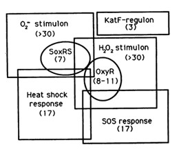
The reaction of hydrogen peroxide with transition metals imposes on cells an oxidative stress condition that can result in damage to cell components such as proteins, lipids and principally to DNA. Escherichia Coli cells are able to deal with these adverse events via DNA repair mechanisms or OxyR and SosRS anti-oxidant inducible pathways which are elicited by cells to avoid the introduction of oxidative lesions by hydrogen peroxide.
Among the systems the OxyR gene interacts with, there is the SOS response.
Since we have not success with UV induction, to test the correct functionality of K079049 and K079050 constructs, they were induced by peroxide hydrogen. Low concentration of (1-3mM) results in SOS gene induction in wild-type cells [Imlay and Linn, 1987; Goerlich et alt. 1989].
The plasmid contained the LexA Operator was transformed into DH5alfa bacteria according to the standard protocol and one colony was picked up from the plate and let it grown overnight in 15ml tube with 5ml LB broth and ampicillin. Cultured colony was diluted in 5ml LB broth with ampicillin and 1ul H2O2 (11M) to have medium with 2.2mM concentration of H202 and 0.1 starting OD.
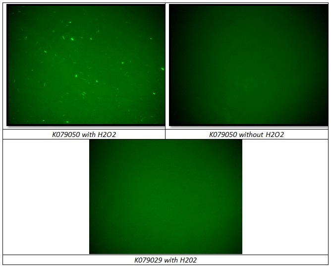
Testing BBa_K079050 construct, two negative controls were used to prove that H202 induction works correctly and that can be used in flip-flop without interferences between Lac Operon and SOS System:
- BBa_K079050 grown in LB medium without H202
- BBa_K079029 grown in LB medium with H202 (Fig. )
Tubes were kept to the dark by using silver paper and let them growing for 2 hours at 37°C. 1 ml of bacteria sample has been collected and transferred inside 1ml tube and spinned at 6000-8000 rpm for 3 minutes. The supernatant was thrown away and the pellet resuspended for the slide preparation.
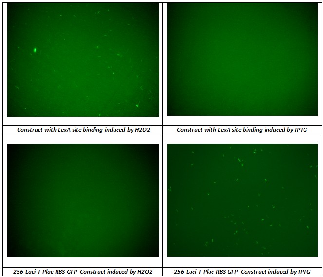
In addition to prove that K079050 construct can be used in the flip-flop circuit without interference between Lac Operon and SOS System a test IPTG and H202 of two previously constructs were done. Fig. shows the results.
As expected the construct with Lex A operator induced by IPTG and Lac-Operon-based-circuit induced by H2O2 didn’t produced GFP synthesis, instead the other two sample correctly induced presented good level of fluorescence.
We conclude that H2O2 induction gives an uniform activity of the regulator promoter (J23100) and the level of promoter activity can be used to set on the memory.
Experimental Evaluation of Lac Operator Site effect on promoter activation
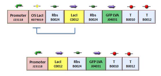
According with the theoretical protocol (procedure for K_index identification) to test operator parts, four circuits were assembled (Fig.1).
BBa_K079020 is a closed loop where GFP expression is auto regulated by the LacI repressor which binds to the Lac operator site. BBa_K079026 (Fig.2) is open-loop circuit lacking the operator site to determinate the maximum fluorescence. In this construct, GFP was spaced from the promoter inserting a LacI gene sequence, to consider abortive transcriptions.
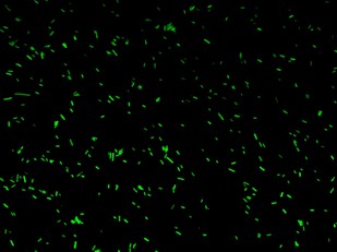
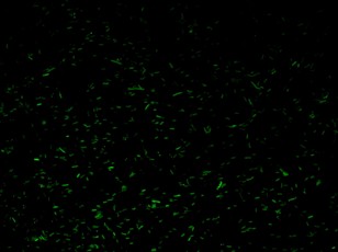
BBa_K079020 and BBa_K079026 were transformed in HL1Blue bacterial cells according to the standard protocol. One colony from each plate was picked up and let grow overnight in LB medium at 37°C. One milliliter for each of the two samples was collected by O/N cultures and spinned at 6000-8000 rpm for three minutes. The supernatant was harvested and the pellet resuspended. Slides were prepared for the fluorescence bacteria image acquisition. For each slide five different view were a acquired. Finally, images were elaborated with the Visual Fluo Bacteria Software. Examples of fluorescence bacteria image are shown in fig. The fluorescence images reveal the repression due to the presence of the Lac operator.
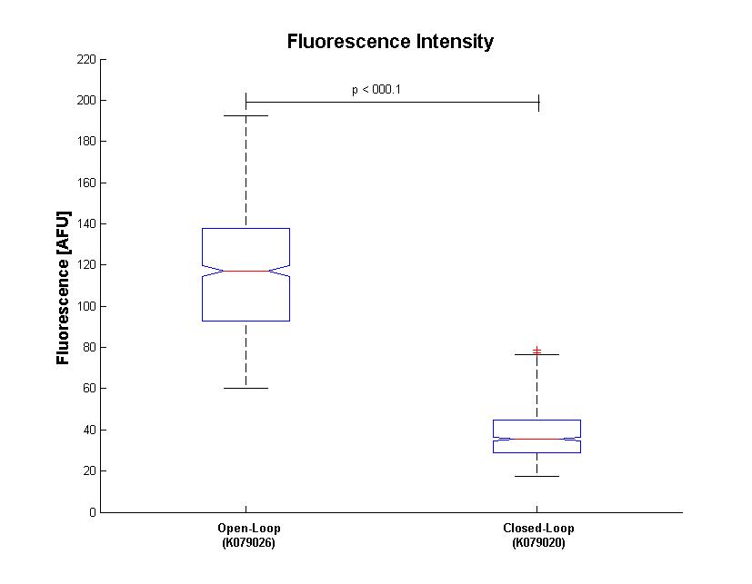
Analysis about the fluorescence distribution is shown in Fig.4 : a matlab boxplot was performed to compare Gaussian distribution between closed and open loop.
Results of fluorescence bacteria analysis by software are reported in tab .The open loop and closed loop circuit fluorescence mean ratio (h factor) can be estimated using the results coming from the Visual Fluo Bacteria Software elaboration for the two circuit views (Fig.3a – Fig.3b).
Finally, a T-Test was performed on data distributions. The probability that open loop and closed loop distribution could be equal is less than 0.001%.
So, it is possible to compute
and h can be used to obtain the value of Ki-index with model equations.
With this parameter , from the Figure 6 (see modeling section 1.5), is possible to estimate Ki-index and it results equal to 4.43. From Figure 4 (see modeling section 1.4) can be chosen the proper value for Kr in order to obtain the bi-stable system.
Homemade UV Illuminator
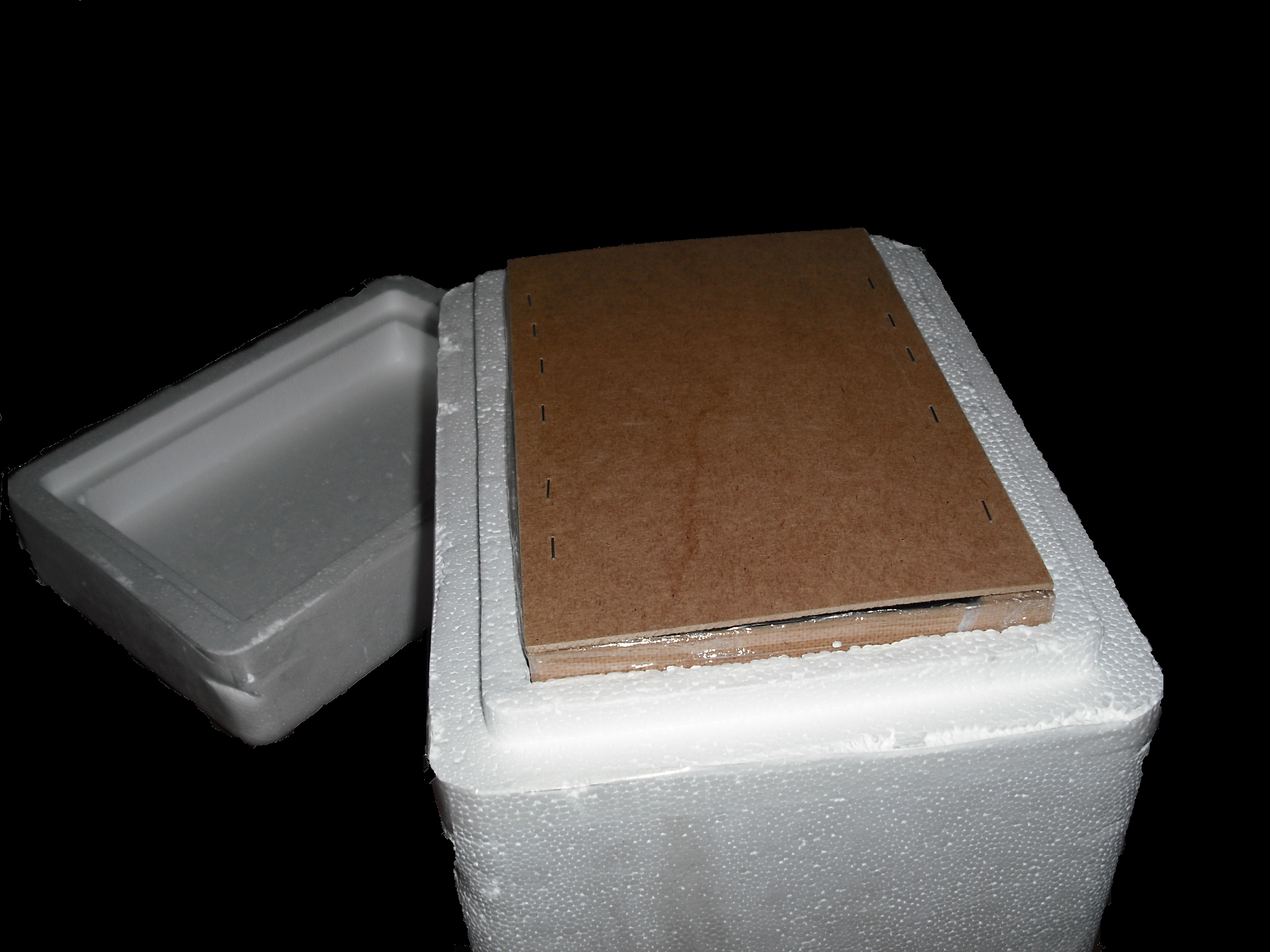
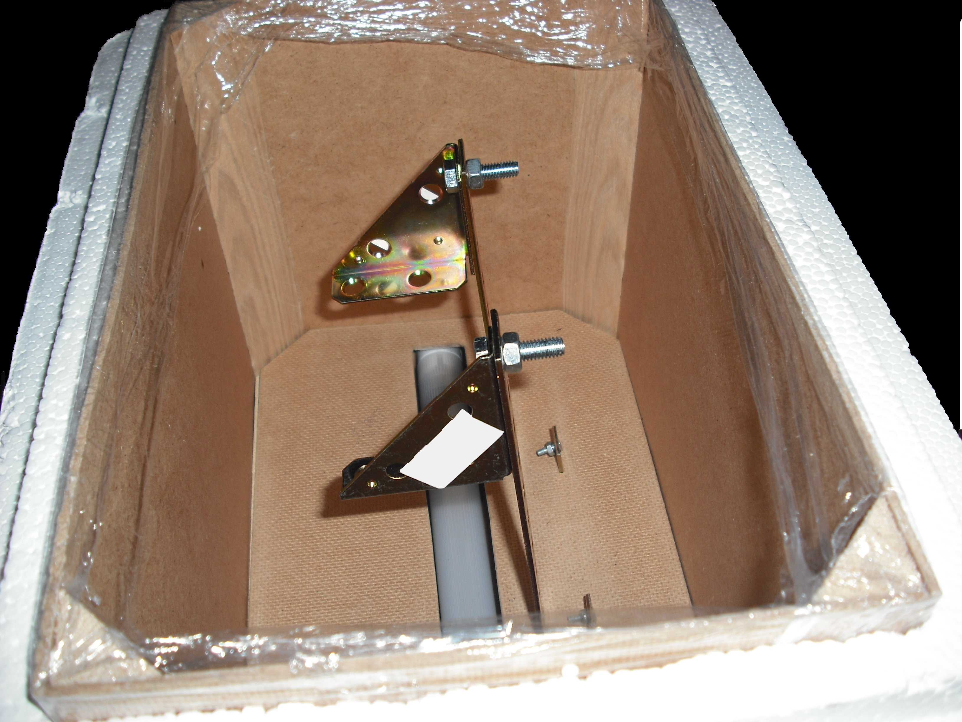
The UV source that we use is a GW6 Sylvania, a lamp that emitt UVC at 253,7nm near the absorption's peak of DNA with an optical output power of 1,6W; to use it safely we built a box of mdf(medium density-fibreboard) that surrounds the lamp and prevent the UVc leakeage, moreover we use a diaphragm that allows passage only to part of the light, absorbing the remainder. We insert in that box two pierced brackets, that permits to choose the distance between the lamp and the sample and then in accord with the Lambert-Beer law's the exposure time. Finally we embedded this structure in a polistyrene box for its handling and greater safety (Figure 2-3).
Gel matrix
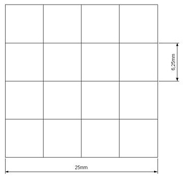
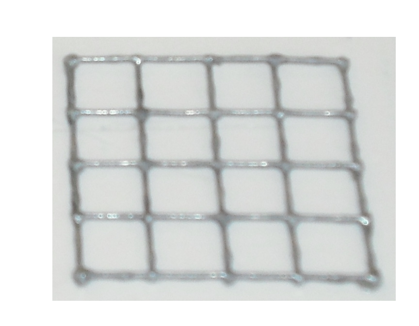
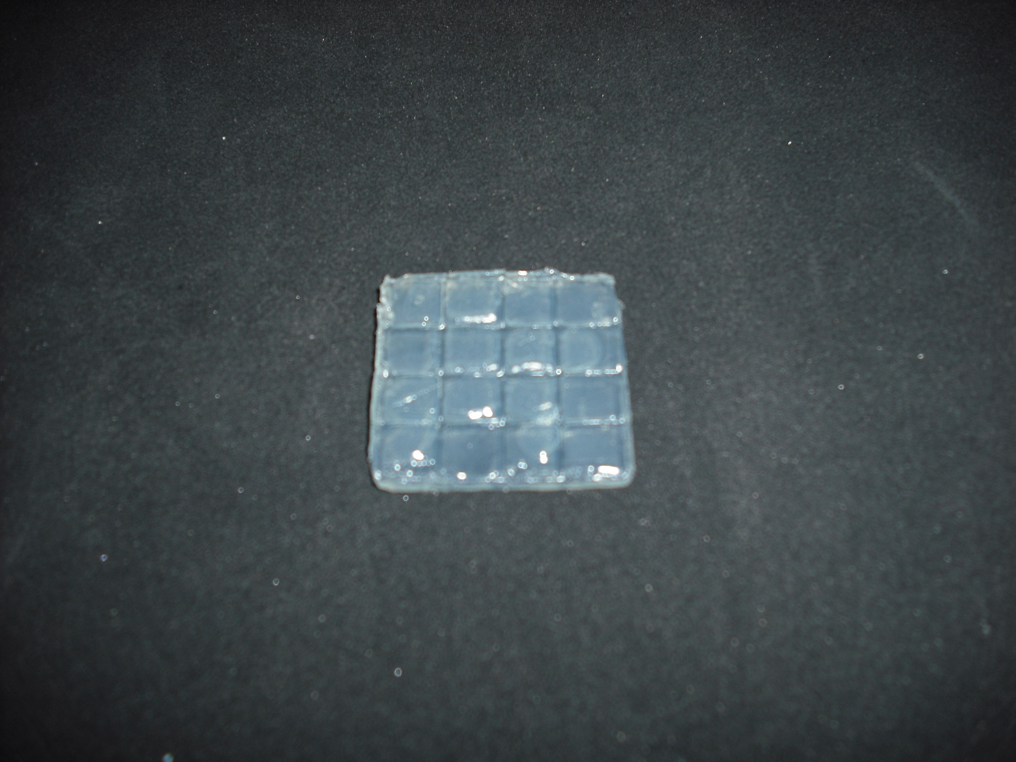
Our project use UV light for its space selectivity, that gives the possibility to irradiate a target zone without interfering with the other. To do that we build a mold to make a matrix of agarose gel;this give us a square of 25mm side's with 16 cells inside where we can locate bacteria( Figure 4 )
Once do that is easy with an optical mask, like those used in photolithography for electronics
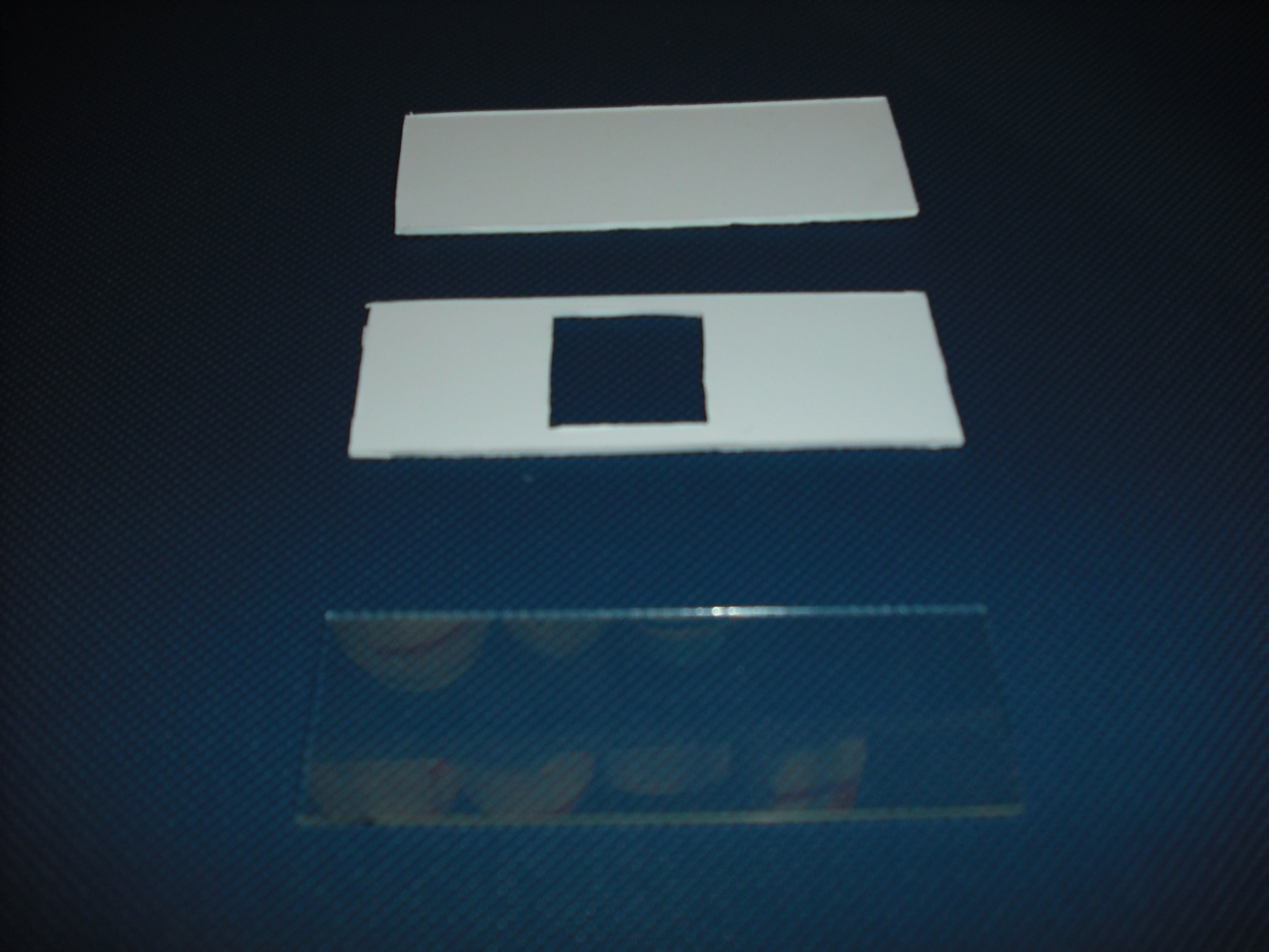
circuits, stimulate only the selected bacteria.To realize this device we use palsticard because it is
very easy to shape and clean( Figure 5 ).
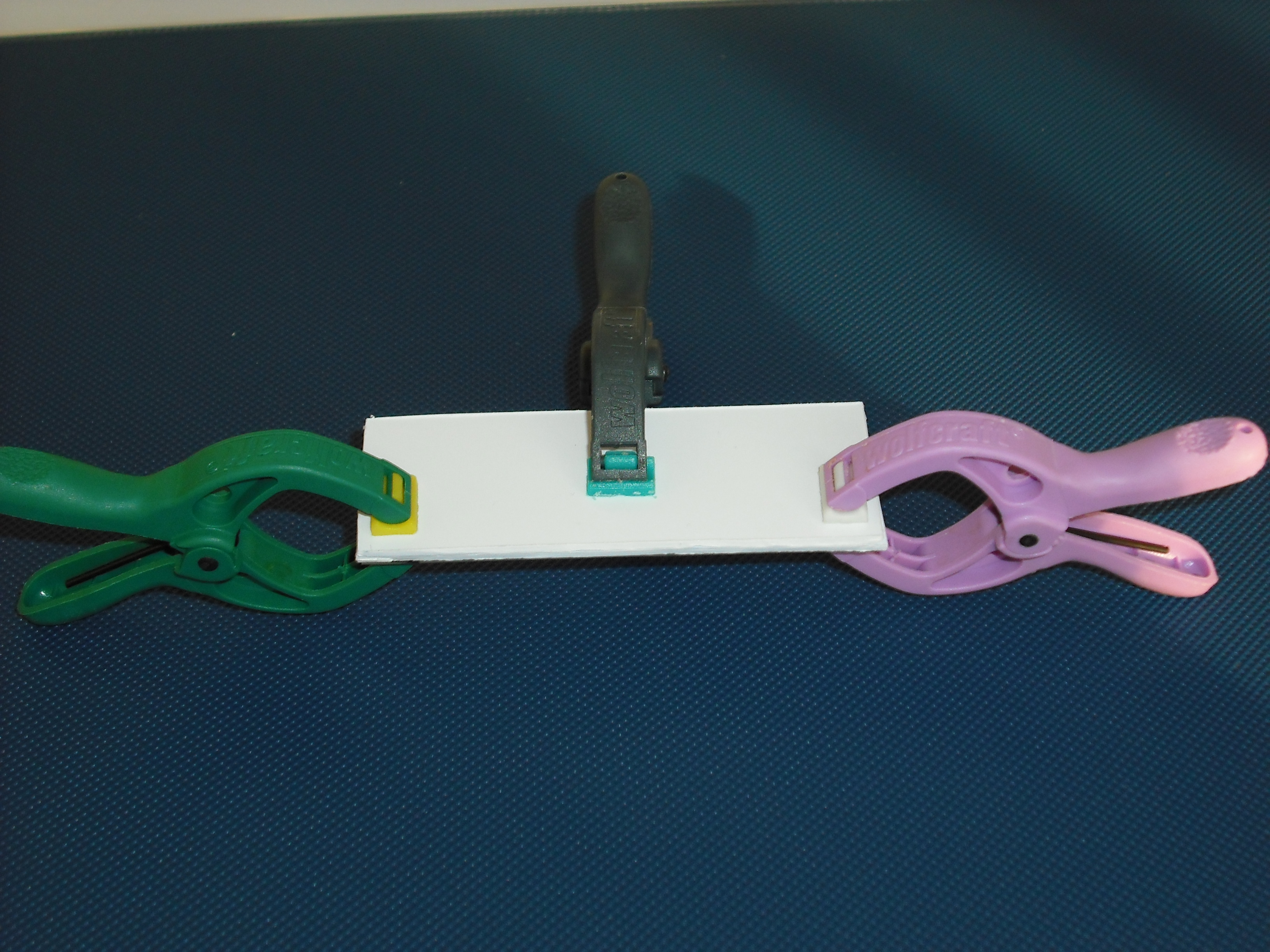
The mold is made of two parts that will form a sandwich with the slide: one will create the shape
of the gel matrix( Figure 6 ) the other is a cover that that will give the picture into gel .
The matrix is obtained through the pressure of the cover part over the mold part( Figure 7 )
and that is the result:
 "
"
