Team:TUDelft/Temperature design2
From 2008.igem.org
Contents |
Design phase II:
Changing the switching temperature of the RNA thermometer
Introducing existing RNA thermometers into Escherichia coli provides us with a number of temperature sensitive switches, all with their own switching temperature. But this only provides a few switching temperatures, which are also relatively close to each other. In order to build a biothermometer, we needed more switching temperatures that have a bigger range. Note, however, that there will always be an upper bound in that the E. coli cannot survive temperatures above 40°C, and a lower bound in that the activity of the cell will drop at low temperatures.
This chapter presents a method that has been used to design RNA thermometer parts that should theoretically switch at a predefined temperature. The method used is based on the data analysis of which the results can be found on the analysis page. It has been used to design two new parts, one that should theoretically be switched on at 27°C ([http://partsregistry.org/wiki/index.php?title=Part:BBa_K115016 BBa_K115016]), and two that should theoretically be switched on at 32°C ([http://partsregistry.org/wiki/index.php?title=Part:BBa_K115017 BBa_K115017]).
Secondary structure stability and switching temperature
The switching temperature of the RNA thermometer depends on the stability of the hairpin structure that surrounds the Shine Dalgarno region (see also Requirements for an RNA therometer). This secondary structure will melt when it is exposed to a certain amount of heat. The more stable the hairpin structure is, the more heat will be needed to melt it, and the less stable the hairpin structure is, the less heat will be needed to melt it. In case of the RNA thermometer, this melting is needed to expose the Shine Dalgarno sequence which will cause the initiation of translation.
In other words, a less stable hairpin structure will melt at a lower temperature than a more stable hairpin and thus, for the less stable hairpin, the translation will initiate at a lower temperature than the more stable one. This way we could theoretically shift the switching temperature to a lower or higher temperature by making the hairpin structure surrounding the SD region less or more stable respectively.
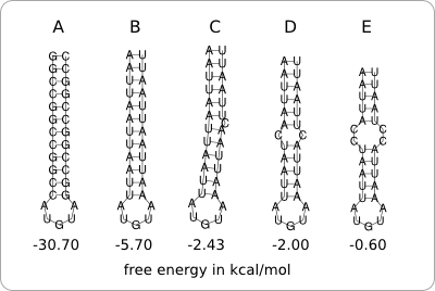
The stability of the hairpin structure depends on the base-pairing nucleotides within the secondary structure. For example, C-G base pairs are very strong, so a hairpin structure containing a lot of those base pairs will be very stable. A-U and U-G base pairs are less strong, so these can be used to destabilize the hairpin structure. The same can be achieved by incorporating bulge loops and internal loops within the hairpin structure (figure 1).
Constraints
There are two things that have to be taken into account. Firstly, adding mutations in order to enforce or weaken the temperature sensitive region can also cause the RNA to fold into a completely different secondary structure. This way it can lose its function as an RNA thermometer. Secondly, there are some constraints to the possible mutations. The start codon and the Shine Dalgarno sequence must off course remain unaltered and in case of a standard biobrick the scar must also be part of the temperature sensitive hairpin.
Design starting point
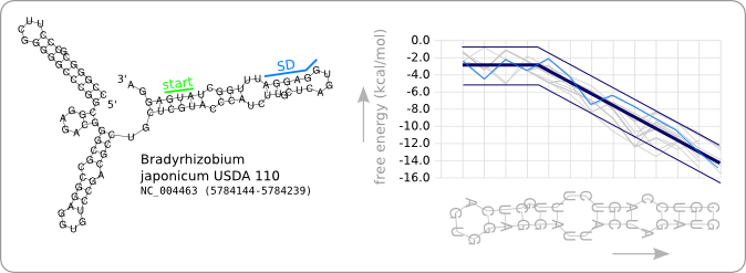
Since we have a number of structures of which we know that they work as an RNA thermometer, the most logical option is to take one of those structures as the starting point for the design of an RNA thermometer with a different switching temperature. The one chosen is a ROSE RNA thermometer from Bradyrhizobium japonicum USDA 110 ([http://www.ncbi.nlm.nih.gov/sites/entrez?Db=genome&Cmd=ShowDetailView&TermToSearch=272 NC_004463]) residing at location [http://www.ncbi.nlm.nih.gov/projects/sviewer/?id=NC_004463.1&v=5784144..5784239 5784144-5784239] within the genome, which is at the 5' side of the gene [http://www.ncbi.nlm.nih.gov/sites/entrez?db=gene&cmd=search&term=NC_004463%20hspb hspB]. There was no specific reason for the choice of this ROSE RNA thermometer, this is just a ROSE RNA thermometer taken from the [http://rfam.sanger.ac.uk Rfam database].
We will call this RNA thermometer a 37°C switch, while it actually reaches maximum translation several degrees higher. The reason that we call it a 37°C switch is because of the characteristic stability profile we found during the analysis, and which is calculated at 37°C. Having a 27°C switch would then mean that this is an RNA thermometer of which the stability profile at 27 degrees is similar to the trend as given in figure 8 of the analysis. This switch should then theoretically be almost fully switched on at 27°C, as is the case for the 37°C version at 37°C.
Figure 2 shows the secondary structure of the chosen RNA thermometer as predicted by RNAfold. Also the stability profile that is characteristic for this RNA thermometer at 37°C is shown in light blue. The thick dark blue line is the trend as found in the data analysis and the thin dark blue lines are design boundaries which will be discussed later in this chapter. The stability profiles of the other 31 ROSE RNA thermometers from the Rfam database are shown in grey.
Design constraints
Having a starting point, we need a way to turn this RNA thermometer into one that switches at a different temperature, and that conforms to the Standard Biological Part standard. This can be achieved by increasing or decreasing the stability of the hairpin structure, as explained at the begin of this page. But, as also mentioned, there are certain constraints that has to be laid upon the design.
Constraints on the sequence
Looking at the nucleotide sequence of the design, there is the constraint that there must be a start codon, a Shine Dalgarno sequence, and a scar present within the sequence. Note that this is the sequence after ligation of the RNA thermometer part to a protein coding part and that the scar and start codon are not part of the RNA thermometer part that we are designing. But since we are interested in the secondary structure of the end product we do have to take them into account. Also the order and distances between these regions are predefined (figure 3).
Constraints on the secondary structure
Extra constraints, which are laid upon the secondary structure of the designed RNA thermometer, are specified in order to 1. simplify the design process; putting restrictions on, for example the length of the hairpin greatly reduces the solution space, making the problem easier to solve, and 2. to keep the secondary structure of the design as close as possible to the secondary structure of the original RNA thermometer. The analysis showed that mutations influence the translation efficiency without loosing its function as RNA thermometer. It is unclear if the same would hold when for example the length of the temperature sensitive hairpin is changed1. The more we change the secondary structure, the bigger the risk that it loses its function as an RNA thermometer.
1During the project a paper from [1] has been published in which it is shown that the length of a temperature sensitive hairpin and the size of its hairpin loop can be varied without loosing the temperature sensitivity.
To keep the secondary structure as close as possible to the original RNA thermometer we state that mutations may only be applied to the temperature sensitive hairpin, the rest of the structure is fixed. For the temperature sensitive hairpin it is stated that the length of the hairpin, the size of the hairpin loop and the location of the hairpin loop must remain the same.
List of constraints
Recapitulating, the list of design constraints is now as follows:
- The sequence before the temperature sensitive hairpin remains unaltered, so mutations are only allowed within the temperature sensitive hairpin.
- The overall structure of the temperature sensitive hairpin must remain the same. This means that the loop at the end should be of the same size and at the same position and the length of the hairpin remains the same. There are no restrictions to the number and locations of internal loops and bulge loops within the double helix region of the temperature sensitive hairpin.
- The start codon, SD sequence, and scar sequence are predefined sequences and are placed at fixed location within the hairpin structure.
These constraints are also captured in figure 3 which can be seen as a template for the design of the temperature sensitive hairpin.
Design algorithm
As specified in the previous section, mutations may only be applied within the temperature sensitive hairpin region. The temperature sensitive hairpin is therefore the only sequence that has to be designed and figure 3 serves as a template for this design.
The data analysis of the known ROSE RNA thermometers has shown a trend within the stability profiles of the temperature sensitive hairpins (figure 8 of the analysis). This trend has been observed for the stability profiles calculated at 37°C, and as already mentioned those RNA thermometers will therefore be called 37°C switches.
To design a switch with a different temperature switching point, for example a 27°C switch, we assume that the stability profile of this RNA thermometer, calculated at 27°C, should be similar to the trend we found for the 37°C switch (calculated at 37°C). In other words, we would like the stability of the temperature sensitive hairpin of the 27°C switch at 27°C, to be the same as the stability of the temperature sensitive hairpin of the 37°C switch at 37°C.
Algorithm
Such a design can be made by fitting the stability profile (calculated at the desired temperature) of the hairpin to the found stability profile trend, taking into account the mentioned constraints in the previous section. The design of a temperature sensitive hairpin that switches at a certain temperature (which is given as input to the algorithm) can be made using an algorithm that acts as follows[1]:
Note that the description of this algorithm is purely illustrative, only showing the principle. For the implementation of such an algorithm, a different approach is needed to make it more efficient (see also RNA Hairpin Designer).
- Take a sequence with the predefined nucleotides (start codon, SD sequence, and the scar) present at the correct locations, the rest of the nucleotides can be filled at random.
- Predict the secondary structure of the RNA thermometer (at the desired switching temperature) to check if it corresponds to the required structure. If not, go to step one.
- Compare the stability profile plot (calculated for the desired switching temperature) of the temperature sensitive hairpin to the trend plot. If it stays within the boundaries that are set at a certain distance form the trend line, a good enough design is found and the algorithm is terminated. Otherwise go back to step one to give it another try.
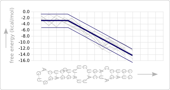
In order to break this optimization algorithm, a conditional check is added to the last step that stops the algorithm when the stability profile of the design fits the trend line good enough. This has been done by specifying boundaries that reside at a certain distance from the trend line (figure 4). The design process is stopped as soon as the stability profile of the design stays completely within the boundaries. Looking at the plot in which the trend line has been observed (figure 8 of the analysis) a boundary at a distance of 2.0 kcal/mol from the trend line seems reasonable.
Manual approach
Because of the restricted time of the project, there was no time to wait for a software implementation of the design algorithm. Therefore a number of parts have been designed manually. The manual design has been done using a less naive approach than the given algorithm. Taking random nucleotides for the nineteen positions that are free to choose is not efficient. The number of possible sequences is enormous while only a small fraction of these will fold into the desired secondary structure.
For the manual approach the total sequence of the RNA thermometer from figure 2 has been taken as starting point. Instead of randomly choosing nucleotides for all the positions that may be mutated, those positions are considered one by one to see if the double helix can be destabilized through mutations of the nucleotides at these positions. For example, at a position where there is a G-C base pair of which the C may be mutated, the C can be mutated to a U, which results in a less stable hairpin. Also a mutation to G or A would be possible in order to incorporate an internal loop, which destabilizes the double helix even further.
After each mutation, the secondary structure has been predicted, using RNAfold, to check if it still folds into the desired structure. When it does, the stability profile has been plotted, using RNAeval and the Stability Profile Plotter, to check if it stays within the trend boundaries.
Result
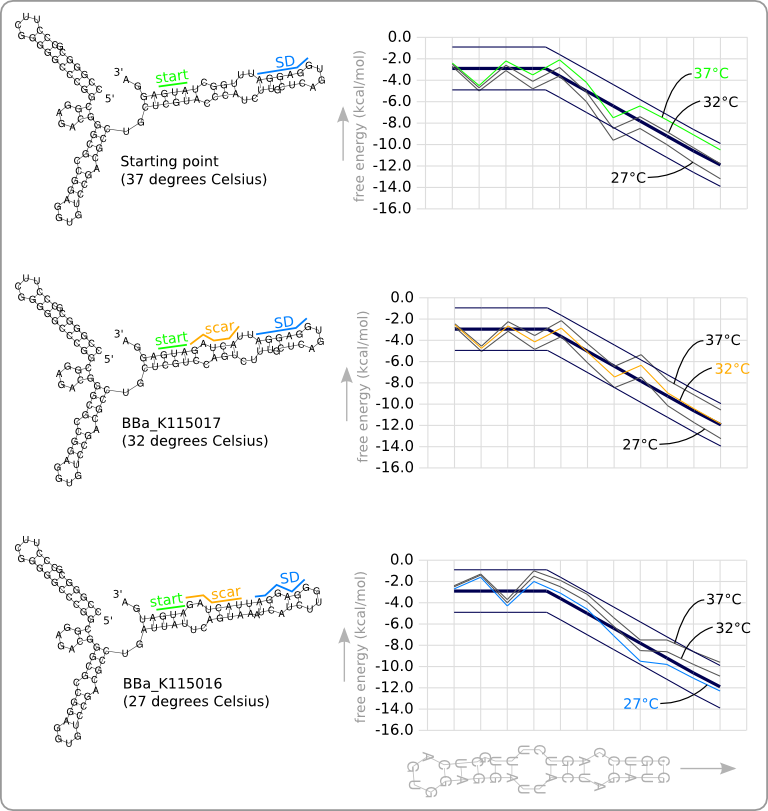
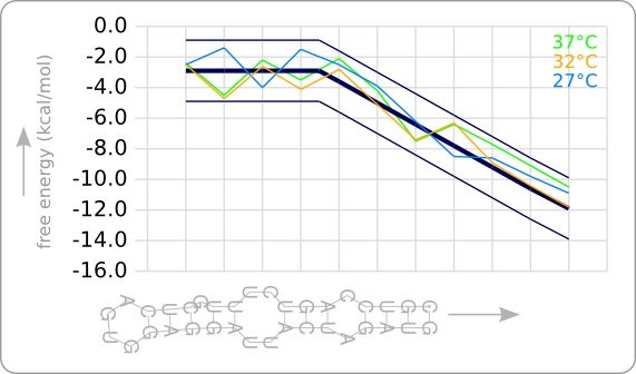
This manual approach has been used to design two RNA thermometers, a 27°C, and a 32°C version (BBa_K115016 and BBa_K115017). The secondary structures of the resulting RNA thermometers are shown in figure 5, together with the stability profiles and the trend line.
The stability profiles of the temperature sensitive hairpins off all three RNA thermometers (calculated at their switching temperature) are also displayed in one plot in figure 6. This shows that each of them has a similar stability at their own theoretical switching temperature.
Temperature sensitive hairpin parts
The only sequence that has to be designed is the sequence of the temperature sensitive hairpin. The rest of the structure is kept intact to stay as close as possible to the secondary structure of the original RNA thermometer that is used as starting point. It has been shown by Chowdhury [2] that a temperature sensitive hairpin on itself, so without the rest of the ROSE structure, also works as a temperature sensitive switch.
Three temperature sensitive hairpins are added to the registry to test if these short sequences can also be used as temperature sensitive switch. These are the temperature sensitive hairpins of the ROSE RNA thermometer as designed in the first design phase ([http://partsregistry.org/wiki/index.php?title=Part:BBa_K115001 BBa_K115001]), and the temperature sensitive hairpins of the 27°C and 32°C switch as designed in the second design phase ([http://partsregistry.org/wiki/index.php?title=Part:BBa_K115016 BBa_K115016] and [http://partsregistry.org/wiki/index.php?title=Part:BBa_K115017 BBa_K115017]). This are the parts [http://partsregistry.org/wiki/index.php?title=Part:BBa_K115020 BBa_K115020], [http://partsregistry.org/wiki/index.php?title=Part:BBa_K115019 BBa_K115019], and [http://partsregistry.org/wiki/index.php?title=Part:BBa_K115018 BBa_K115018] respectively.
If these short hairpins happen to be enough to get a working RNA thermometer, this would be a nice starting point for a third design phase in which these small parts are further optimized. For us, there's not enough time left to do this, but it could be a good starting point for a next years iGEM project.
References
- ^ Juliane Neupert and Daniel Karcher and Ralph Bock. Design of simple synthetic RNA thermometers for temperature-controlled gene expression in Escherichia coli. Nucleic Acids Research, 1-9, 2008. [http://www.ncbi.nlm.nih.gov/pubmed/18753148 PMID:18753148]
- ^ Saheli Chowdhury, Curdin Ragaz, Emma Kreuger, and Franz Narberhaus. Temperature-controlled Structural Alterations of an RNA Thermometer. The Journal of Biological Chemistry, 278(48):47915-47921, 2003. [http://www.ncbi.nlm.nih.gov/pubmed/12963744 PMID:12963744]
 "
"
